8 e10a-usb interface, Functional overview – Renesas M3A-HS25 User Manual
Page 24
Functional Overview
2.8 E10A-USB Interface
REJ10J0952-0100
2
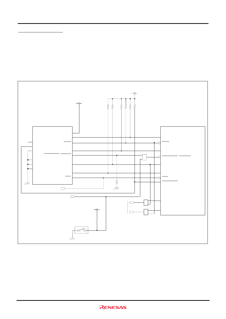
2.8 E10A-USB Interface
The M3A-HS25 has a 14-pin H-UDI connector included in it for connection to the E10A-USB.
TMS pins and TRST pins of SH7125 are multiplexed with transmit/receive pins of SCI channel 1. When H-UDI
connector is used, make sure that the settings of JP3 and JP4 are set to 1-2 side.
In addition, H-UDI pin of SH7125 is connected to the extension connector, do not use the applicable pins of the
extension connector when debugging with the H-UDI connector.
Figure2.8.1 shows the block diagram of E10A-USB interface.
Reset Signal
SH7125
(GND)
GND
GND
GND
TRST/PA3/IRQ1/RXD1
TMS/PA4/IRQ2/TXD1
TCK/PA7/TCLKB/SCK2
TDI/PA8/TCLKC/RXD2
TDO/PA9/TCLKD/TXD2/POE8
ASEBRKAK/ASEBRK/FWE
ASEMODE0
RES
H-UDI connector
(J1)
TRST
TMS
TCK
TDI
TDO
ASEBRKAK/ASEBRK
N.C.
RES
GND
Vcc
1
2
UVCC
3
4
5
6
7
8
9
10
12
13
14
11
Vcc
JP2
1
2
3
JP3
1
2
3
1
2
3
JP4
Serial Port
Connector (J2)
PE2/TIOC0C/TXD0
PE1/TIOC0B/RXD0
SW4-1
Extension
Connector (J7)
Vcc
Figure2.8.1 Block Diagram of E10A-USB Interface
Rev.1.0 July 21, 2006
2-10