Ricoh R5C841 User Manual
Page 66
R5C841 PCI-CardBus/IEEE 1394/SD Card/Memory Stick/xD/ExpressCard Data Sheet
12345
2004
R
EV
. 1.10
5-13
I/O Write
(VCC_ROUT= 1.65~1.95V, VCC_3V=3.0~3.6V, Ta=0~70ºC)
Symbol Parameter
Min
Max
Unit
Note
CADR [25:0], REG#
t9a
Setup Time, CADR [25:0] and REG# before
IOWR # Low
Tsu-20 ns 1,3
Tsu=2~7Tcyc
Programmable
t9c
Hold Time, CADR[25:0], REG# and CE[2:1]#
after IOWR # High
Thl-10 ns 1,3
Thl=1~7Tcyc
Programmable
IOWR#
t9b
Pulse Duration, IOWR# Low
Tpw-20
ns
1,3
Tpw=3~31Tcyc
Programmable
CE[2:1]#
t9h
Valid Delay, CADR [25:0] and REG# to CE [2:1]#
1Tcyc-10
ns
1
CDATA
[15:0]
t9d
Setup Time, CDATA [15:0] before IOWR# Low
Tsu-2Tcyc-10
ns
1,3
Tsu=3~7Tcyc
Programmable
t9e
Hold Time, CDATA [15:0] after IOWR# High
Thl-10
ns
1,3
Thl=1~7Tcyc
Programmable
WAIT#
t9f
Hold Time, IOWR# Low after WAIT# High
1Tcyc+0
ns
3
t9g
Valid Delay, IOWR# Low to WAIT# Low
50
ns
IOIS16#
t9j
Valid Delay, CADR [25:0] and REG# to IOIS16#
Low
50
ns
Note1: Tcyc is PCICLK cycle time. (Typically 30ns)
Note3: Tsu, Tpw, Thl can be programmed by setting 16-bit I/O Timing 0 register.
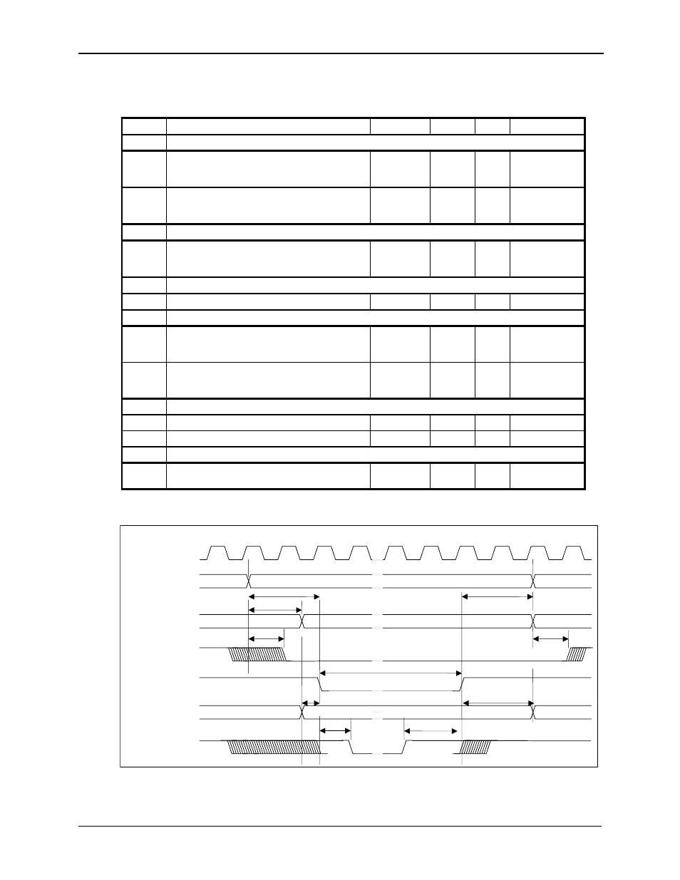
16-bit Card I/O Write Timing
WAIT#
CDATA
IOWR#
CADR,REG#
t9j
t9j
t9f
t9g
t9d
t9b
PCICLK
CE1#,CE2#
IOIS16#
t9h
t9e
t9a
t9c
16-bit Card I/O Write Timing