21 led# output – Ricoh R5C841 User Manual
Page 46
R5C841 PCI-CardBus/IEEE 1394/SD Card/Memory Stick/xD/ExpressCard Data Sheet
12345
2004
R
EV
.1.10
4-21
4.20.3.6 xD Picture Card Configuration Space
Address
Bit7 Bit6 Bit5 Bit4 Bit3 Bit2 Bit1 Bit0
74h Subsystem
Vendor ID[7:0]
75h Subsystem
Vendor ID[15:8]
76h Subsystem
ID[7:0]
77h Subsystem
ID[15:8]
78h XDLED
toLED1#
XDLED
toLED0#
-
-
-
-
-
-
79h
Write Enable 0xFD
7Ah
-
-
-
-
-
- CLKRUNDis,
XDPWRPol
7Bh
-
- LEDDurationSel[1:0] - INTSEL[1:0] -
7Ch Counter
cut
-
-
-
-
-
Card Detect Mode[1:0]
7Dh
-
-
-
-
-
- CLK
selection -
7Eh
-
-
-
-
-
- PMETrgIn
(Card
Inserted by
XDCD#)
PMETrgRM
(Card
Removed by
XDCD#)
4.21 LED# Output
The R5C841 can output the activity signals of the PC card, the 1394OHCI, the SD Card, the
Memory Stick and the xD PictureCard, as LED0#, LED1# and LED2#. The R5C841 uses UDIOx
pins as LED0#/1#/2#. See the PC Card Misc Control 4 (Config. (Func.0) A4h) register for use
these pins. The default of the LED signal is ‘Low’ active. But, setting the LED Polarity bit (Config,
(Func.0) 82h bit11) to “1b” enables to set the LED signal to ‘high’ active. This bit is common to the
PC card, the 1394 OHCI, the SD Card, the Memory Stick and the xD Picture Card.
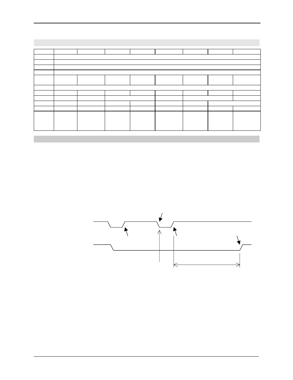
The LED signal is asserted at the same time the trigger of its signal is asserted. And the internal
counter works after the trigger is deasserted. In default, the LED signal is kept for 64msec after
the deassertion of the trigger, and is deasserted. When the trigger is reasserted in operation of
the counter, the counter is cleared and restarted to count up at the same time the deassertion of
the LED signal. See the below chart.
The LED Output Duration is selected from among 64msec(default), 1msec and No Duration time
(through the trigger). The card and the 1394 have the different registers for selecting each other
(See the following). The trigger signals for them also are different.
The R5C841 uses a counter operating PCLK for the LED Output Duration and therefore a stop
request of PCLK by the CLKRUN protocol is refused in operation of the counter. When PCLK
must be stopped for 64msec on system, modify the LED Output Duration.
LED0#: PC_Card LED# + 1394 LED# + SD_Card LED# + Memory Stick LED# + xD LED#
LED1#: PC_Card LED# + 1394 LED# + SD_Card LED# + Memory Stick LED# + xD LED#
LED2#: 1394 LED#
Count up
Counter Start
Not Count up
Counter Reset
Counter Restart
LED Output Duration
The LED output
The LED trigger