Module status leds, Line modules (lm), 1 module status leds – RuggedCom RUGGEDBACKBONE RX1501 User Manual
Page 12: 3 line modules (lm), Modules, see, Section 2.3, “line modules (lm)
Chapter 2
RuggedBackbone™ Modules
RuggedBackbone™ RX1501
Installation Guide
6
Module Status LEDs
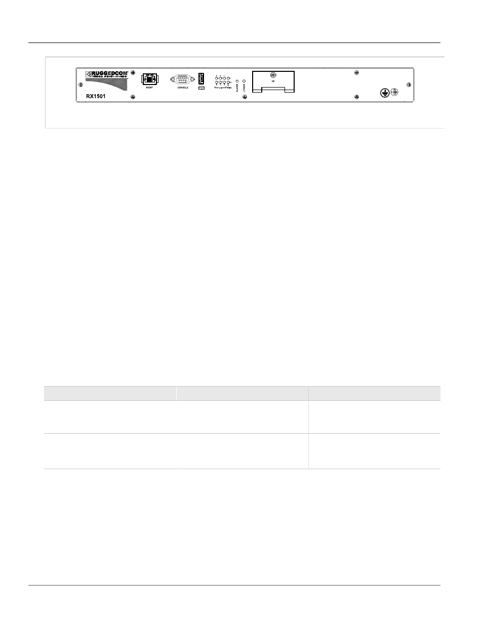
Figure 2: Front View
Other Front Panel features include:
• Utility USB port
• Power module indicator LED
• Line module indicator LEDs
• Alarm Indicator LED, which indicates system alarm status.
• Lamp Test / Alarm Cutoff (LT/ACO) button
• Removable 1GB Compact Flash (CF) card, which contains active and fallback installations of the ROX
operating system, along with the configuration database and other system data
• Chassis ground connection
For more information on connecting to the ports on the front panel, see the following topics:
• Serial Console:
Section 3.4, “Serial Console Port”
• Management Ethernet Interface:
Section 3.7, “Copper Ethernet Ports”
• Critical Alarm (Failsafe) Relay Interface:
Section 3.3, “Critical Alarm Wiring”
Section 2.2.1
Module Status LEDs
The front panel module status LEDs provide the following information:
Table 1: Module Status LED Indications
LED
Purpose
Description
PM1
Indicates power supply status.
I = Power supply is receiving input voltage.
O = Power supply is providing
output voltage to the RX1501.
LM 1 through 6
Indicates the line module status.
Green = OK
Orange = Warning alert
Red = Configuration error
Section 2.3
Line Modules (LM)
The RuggedBackbone™ RX1501 supports six line modules in slots LM1 through LM6. Several types of line
modules may be ordered, depending on the type, speed and number of Ethernet ports required.
The following illustrations show the typical port configurations and connectors available for RX1501 line modules.
For complete information on the available line modules, refer to the RuggedBackbone™ RX1501 data sheet.