Important – Renesas Compact Emulator M30620T-CPE User Manual
Page 32
( 32 / 52 )
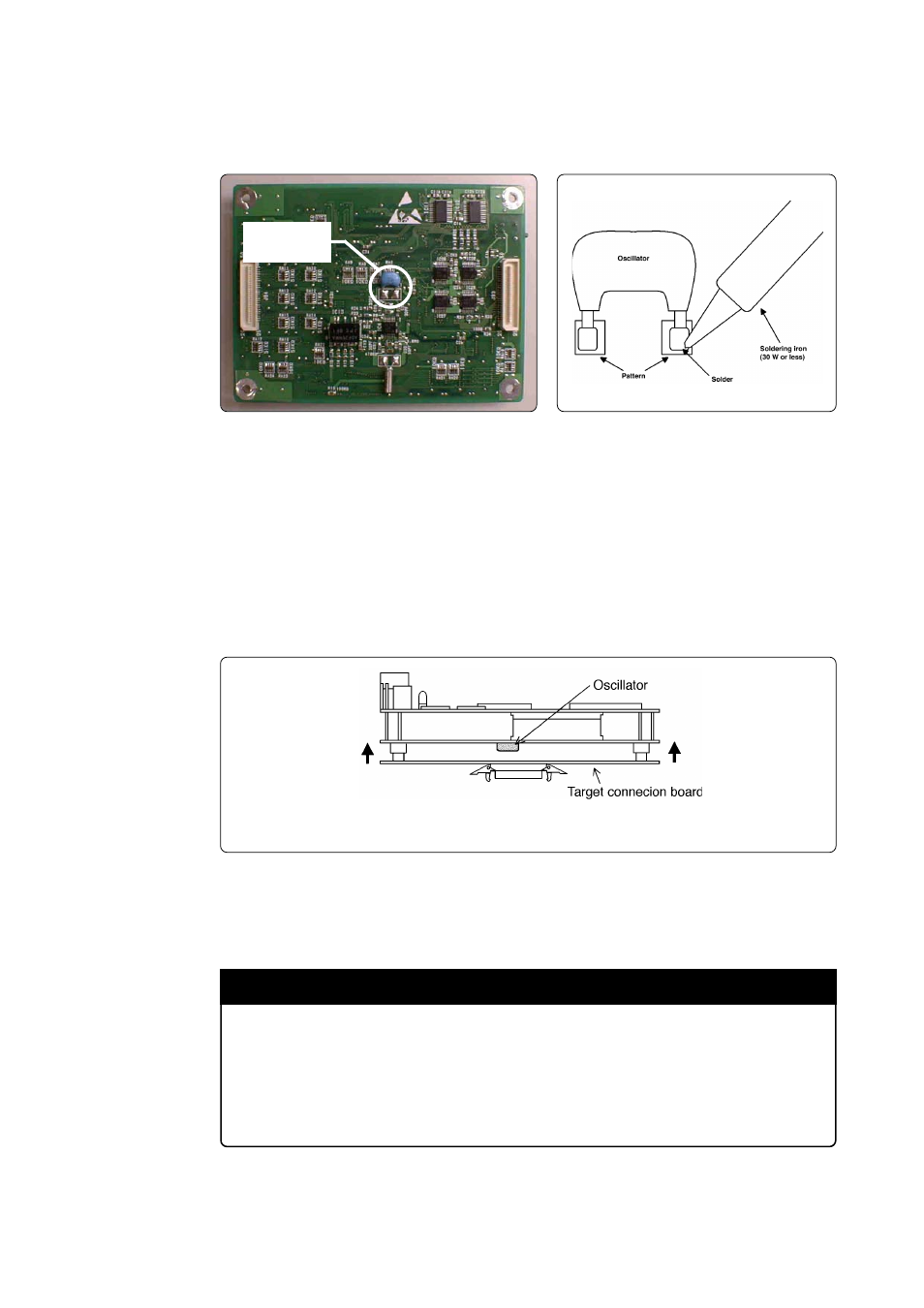
(3) Remove the oscillator
Figure 3.4 shows the position of the oscillator for the main clock. Remove the oscillator using
a soldering iron. Be careful not to break the other part.
Figure 3.6 Connecting the target connection board (side view)
(6) Check the operation of the system
After connecting the target system, start up the emulator system. If the emulator starts up
normally, the replacement is completed.
(4) Connecting the Oscillator
Solder the included 16MHz oscillator in the place of the older oscillator (see Figure 3.4).
Solder the oscillator so that the label can be read.
(5) Connecting the target connection board
Check the oscillator is properly connected. If it is, connect the target connection board to the
emulator. The connectors are designed so that they cannot be inserted in the opposite
direction, therefore check orientation before inserting the oscillator. Also, insert the oscillator
without applying excessive force.
Insert an equal amount of force to the connectors on each end of the target connection board when inserting the board.
Note: Do not insert excessive force to the connectors. Excessive force can break the connectors.
IMPORTANT
Notes on Replacing Internal Oscillator Circuit of Emulator:
• When a 16MHz oscillator is installed, the self-check cannot be executed, because it
must be done with the target system not connected. During standalone operation, the
emulator operates at 3.3 V, which exceeds the guaranteed operating frequency of the
MCU.
Figure 3.4 Position of oscillator for main clock
(bottom view after removing target connection board)
Figure 3.5 Removing an oscillator
Oscillator for
main clock