Installation, Standard flush door, Optional flush trim – Regency Gas Insert U35-NG1 User Manual
Page 12: Flush louvers
12
U35 FPI Direct Vent Gas Insert
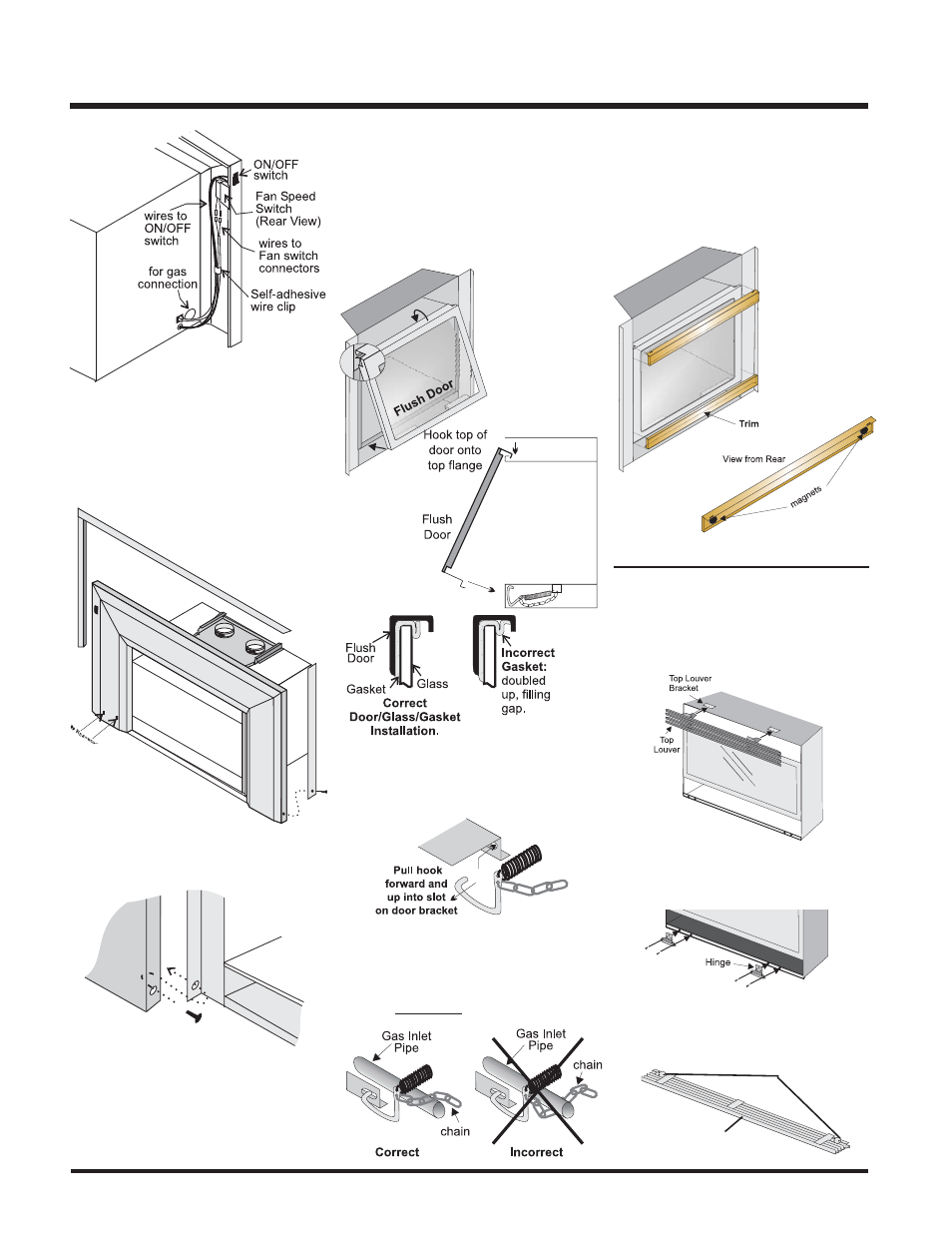
Diagram 4
Diagram 5
Diagram 3
INSTALLATION
9) Attach the brass trim to the faceplate by
drilling a 1/8" hole through into the faceplate
using the hole in the trim as a guide. Fasten
the trim to the faceplate panels using the
plated screws. Diagram 4.
10) Attach the faceplate panels to the insert
body using the 4 remaining black screws.
Diagram 5.
11) Push the Regency logo plate into the
two holes in the bottom left corner of the
faceplate. See Diagram 4.
Diagram 6
Use the hook to pull the spring out until you
can put the hook into the slot on the bottom
door bracket. Repeat for 2nd spring. See
diagram 8.
Diagram 8
Diagram 7
STANDARD
FLUSH DOOR
The standard fl ush door comes with a black
frame. To install the frame, simply hook the top
door fl ange onto the top of the unit and swing
the door towards the unit, diagram 6. Be careful
that the glass gasket does not roll up; there must
be a gap between
the gasket and the
door lip to ensure
that the door sits
securely on the
unit. Diagram 7.
To remove the fl ush door, reverse the above
steps.
NOTE: The chain must rest on TOP of the gas
inlet pipe never under it.
OPTIONAL FLUSH TRIM
Attach 2 round magnets to the back of the top
trim piece and the other 2 to the bottom trim
piece, then attach trim to the top and bottom
of Flush door.
FLUSH LOUVERS
2) Install the Spring Hinges on the left and right
side of the bottom of the Firebox using 2
screws per hinge.
3) Place the Bottom Louver near the hinge. Flip
hinge over the Bottom Louver and secure
using 3 screws.
Bottom Louver
Hinge
Location
1) The top louver is held in place by friction fi t,
if the louver needs to be adjusted; bend the
bracket out as shown in the diagram.