Raypak RAYTHERM 0133-4001 User Manual
Page 14
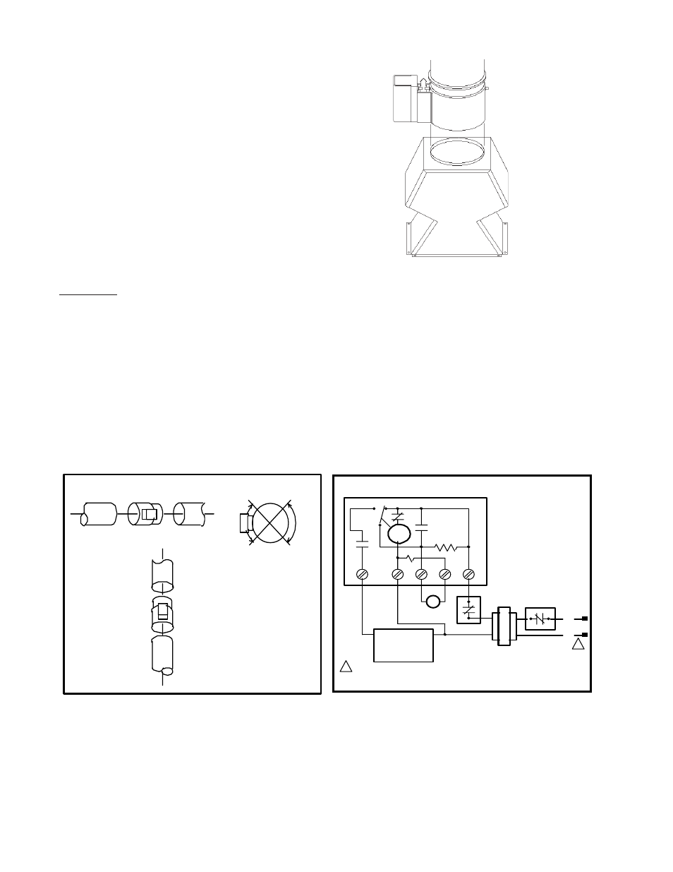
VENT DAMPER INSTALLATION
(MODELS 133 THROUGH 261)
WHERE REQUIRED
LOCATION
The vent damper must be located in the vent so
that it serves only the appliance for which it is intended.
If improperly installed, a hazardous condition, such
as an explosion or carbon monoxide poisoning, could
result. Make certain that it is mounted in an accessible
location at least 6 inches from any combustible mate-
rial or the heat exchanger, and that the position indica-
tor is in a visible location.
The vent damper must be installed after the appli-
ance drafthood, as close to the drafthood as practi-
cable, and without modification of the drafthood.
Fig. # 8182.0
VENT DAMPER INSTALLATION
VENT DAMPER GENERAL WIRING DIAGRAM
Fig. # 8183.0
Fig. # 8615.0
WARNING: Do not use thermally actuated vent dampers on a modulating boiler. To do so, may result in
asphyxiation. Use only a mechanically actuated vent damper device that is electrically interlocked with the
modulating boiler operation.
On vertical vents, the vent damper may be mounted with the actuator in any position. On horizontal vents,
do not mount the actuator either directly above or directly below the vent pipe; mount the vent damper actuator
to the side of the vent.
The vent damper is set up for a continuous pilot system. If the vent damper is installed on an Intermittent
Pilot or Direct Spark Ignition equipped system, the energy savings of the vent damper can be improved by
plugging the hole in the vent damper blade using the knockout plug, Part No. 105612R, provided in the parts
envelope.
DO NOT plug the hole if installing the vent damper on a continuous pilot system as this will create a hazard.
NO
YES
NO
YES
INSTALL VENT
DAMPER WITH
ACTUATOR TO
SIDES OF VENT
ONLY. DO NOT
MOUNT ABOVE OR
BELOW VENT.
TO CHIMNEY
TO BOILER
D808
FLOW >
HORIZONTAL INSTALLATION
TO CHIMNEY
TO BOILER
D808
VERTICAL
INSTALLATION
ACTUATOR MAY BE
INSTALLED IN ANY
POSITION ON
VERTICAL PIPE.
Motor
End
Switch
C.
N.O.
N.C.
1K2
1K1
R
1R
1K3
1
2
3
4
5
D808
Thermostat or
Controller
Dual Valve
Combination Gas
Control or
Ignition System
Optional Limit
Location
Limit
Transformer
L1
(Hot)
L2
1
1
Yellow Blue
Power supply provide disconnect me
ans an overload protection as requ
ired.
Black Orange Red
14
Note: Model 133 drafthood shown.
Power supply provide disconnect means an overload protection as required.