Raypak RAYTHERM 0133-4001 User Manual
Page 13
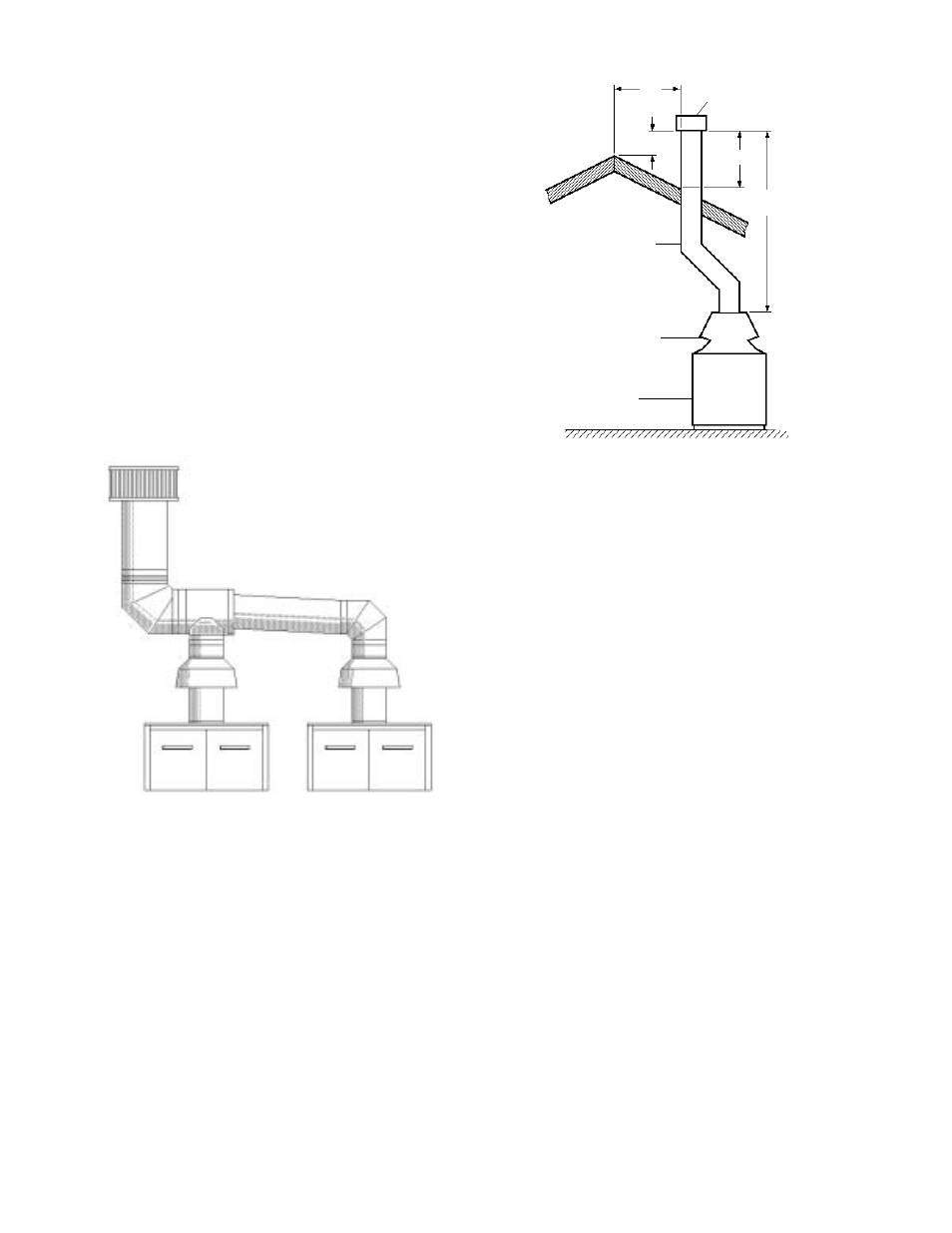
Vent stack shall be at least 5 ft. in vertical height
above the drafthood outlet. The vent cap location shall
have a minimum clearance of 4 feet horizontally from,
and in no case above or below, unless a 4-foot horizon-
tal distance is maintained, from electric meters, gas
meters regulators and relief equipment.
The weight of the vent stack or chimney must not rest
on boiler drafthood. Support must be provided in com-
pliance with applicable codes. The boiler top and
drafthood must be readily removable for maintenance
and inspection. Vent pipe should be adequately sup-
ported to maintain proper clearances from combustible
construction.
Type "B" double-wall or equivalent vent pipe is rec-
ommended. However single-wall metal vent pipe may
be used as specified in the latest edition of the National
Flue Gas Code ANSI Z223.1.
10' or less
5' min.
2' min.
2' min.
Vent Cap
Vent Pipe
Drafthood
Heater
appliance not connected to the common venting
system. Turn on any exhaust fans, such as range
hoods and bathroom exhausts, so they will oper-
ate at maximum speed. Do not operate a summer
exhaust fan. Close fireplace dampers.
(d) Place in operation the appliance being inspected.
Follow the lighting instructions. Adjust thermostat
so appliance will operate continuously.
(e) Test for spillage at the drafthood relief opening
after 5 minutes of main burner operation. Use the
flame of a match or candle, or smoke from a
cigarette, cigar or pipe.
(f) After it has been determined that each appliance
remaining connected to the common venting sys-
tem properly vents when tested as outlined above,
return doors, windows, exhaust fans, fireplace
dampers and any other gas burning appliance to
their previous conditions of use.
(g) Any improper operation of the common venting
system should be corrected so that the installation
conforms with the latest edition of the National Fuel
Gas Code, ANSI Z223.1. When re-sizing any
portion of the common venting system, the com-
mon venting system should be re-sized to
approach the minimum size as determined using
the appropriate tables in Part 11 of the National
Fuel Gas Code, ANSI Z223.1.
For special venting applications that require reduced
vent sizes and through-the-wall venting, the Type D
Induced Draft Assembly can be used. Consult the
factory or your local Raypak representative.
Manifolds that connect more than one
boiler to a common chimney must be
sized to handle the combined load. Con-
sult available guides for proper sizing of
the manifold and the chimney. At no time
should the area be less than the area of
the largest outlet.
Fig. #8119.0
At the time of removal of an existing boiler, the following
steps shall be followed with each appliance remaining
connected to the common venting system placed in
operation, while the other appliances remaining con-
nected to the common venting system are not in
operation.
(a) Seal any unused openings in the common venting
system.
(b) Visually inspect the venting system for proper size
and horizontal pitch and make sure there is no
blockage or restriction, leakage, corrosion and
other deficiencies which could cause an unsafe
condition.
(c) Insofar as is practical, close all building doors and
windows and all doors between the space in which
the appliances remaining connected to the com-
mon venting system are located and other spaces
of the building. Turn on clothes dryers and any
Fig. #7043.1
13