Table12. led descriptions (continued), Figure 1-2, Table 1-2 – NETGEAR XM128 ISDN User Manual
Page 24: Led descriptions -4, Figure, 4 introduction, Table 1-2. led descriptions
Reference Guide for the Model XM128 ISDN Digital Modem
1-4
Introduction
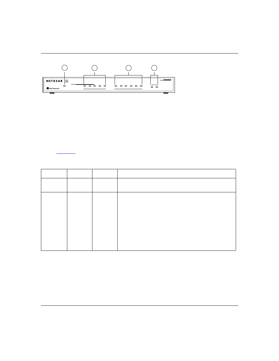
Key:
1 = PWR (power) LED
2 = ISDN LEDs
3 = RS-232 COM LEDs
4 = PHONE 1 and PHONE 2 LEDs
Figure 1-2.
Front panel of the Model XM128 modem (with U interface)
LEDs on the front panel of the Model XM128 modem allow you to monitor and diagnose the
device.
describes each LED.
Table 1-2.
LED descriptions
Label
Color
Activity
Description
PWR
(Power)
Yellow
On
Power is supplied to the modem.
ISDN LEDs:
D
Green
On
The ISDN link on the D channel is active.
Blinking
The modem is attempting to make a connection to the switch.
B1
On
A connection is established to the B1 channel.
B2
On
A connection is established to the B2 channel.
AA
On
The Model XM128 modem is in the automatic answering mode.
CP
Blinking
An incoming call is ringing.
On
Compression is active on either of the B channels.
7847MEA
DTR
DSR
RTS
CTS
TD
D
PWR
B1
B2
AA
CP
ISDN
RD
1
2
ISDN
Digital Modem
INTERFACE
128Kpbs
MODEL
XM128
U
COM
2
3
4
1