NEC GT2000 User Manual
Page 58
E-58
Selecting the Various Items and Switchers
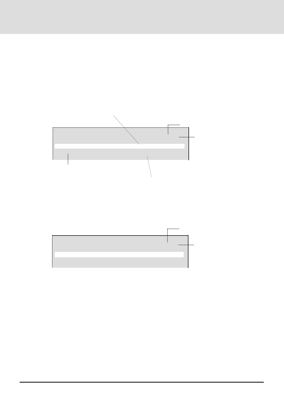
• Selecting User Memory
No ......................... List number
Name .................... Signal name entered by the user
Source .................. This is the set input mode.
(RGB 1, RGB 2, YCbCr1, YCbCr2, VIDEO, and S-VIDEO)
Slot ....................... This is the slot number of the channel. It is termed the channel in this manual.
User Memory
P01/10
No
Name
Source Slot
Lock
00
CUTOM 0007
RGB1
04
On
01
CUTOM 0008
RGB2
07/08
Off
02
Currently selected page
Total number of pages
*
The [*] display appears when the skip setting is on.
07/08 indicates the selection of the equipment that is connected to the number 8 slot of
the master switcher, which is connected to the number 7 slot of the slave switcher.
04 indicates the selection of the equipment that is connected to the number 04 slot of the switcher.
Lock ...................... This is the on/off setting of the auto scan function at the time of input signal switching. It is selected
with the edit menu.
• Selecting Channel Memory
In user memory, the slot specification differs.
Channel Memory
P01/10
No
Name
Source
Lock
00
CUTOM 0007
RGB1
On
01
CUTOM 0008
RGB2
Off
Currently selected page
Total number of pages
In channel memory, the memory number becomes the channel number, which corresponds with the slot number of the switcher.
In signal registration, this number is selected and registration is made to this number.
Settings will differ depending on the switcher connection method. See "Changing the Slot Number of the Switcher (slot)
Switcher Control" on Page E-67.
When the Setting is [SW 1 Level] (One Unit)
When the Setting is [SW 1 Level] (One Unit)
Channel numbers 10 through 19 correspond with switcher slot numbers 01 through 10. (Note that channel 10 will be slot 10, and
channel 11 will be slot 01.)
When the Setting is [SW 2 Level] (Two or More Units)
Channel numbers 00 through 09 correspond with slot numbers 1 through 10 of the slave switcher that is connected to slot 10 of
the master switcher.
Channel numbers 10 through 19 correspond with slot numbers 1 through 10 of the slave switcher that is connected to slot 1 of the
master switcher.
Channel numbers 90 through 99 correspond with slot numbers 1 through 10 of the slave switcher that is connected to slot 9 of the
master switcher.