Minimum mantel clearances, Ab c – Napoleon Fireplaces GD36PTR User Manual
Page 26
26
W415-0210 / R / 02.27.08
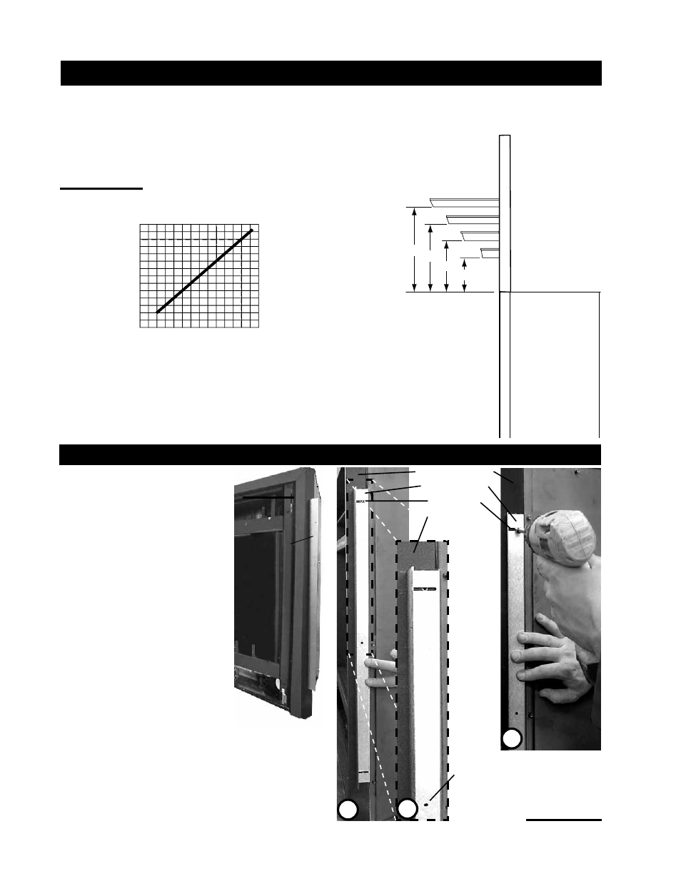
NAILING
TAB
FIGURE 52
1. Attach the nailing tabs to the corner posts
using the 2 sheet metal screws sup-
plied. Secure through the centre of the
top and bottom slots in the nailing tab
and then through the existing holes in
the corner posts.
If there are no existing holes, follow
these instructions:
Position the nailing tab so that the front
face is offset with the front edge of
the corner post (approx. ½"). Centre
the nailing tab vertically on the corner
post.
Figure 53a.
Drill through the centre of the top and
bottom slots in the nailing tab. Secure
using the two sheet metal screws sup-
plied. This allows the nailing tab to slide
back and forth for desired framing.
Figure 53b.
2. To determine the fi nal location of the nailing tab
you must fi rst determine the thickness of your fi nishing
material (i.e. drywall). This will determine the dimension from
the front edge of the corner post to the nailing tab. Once the
nailing tab is in the desired location, drill through the centre
hole of the nailing tab. Secure with a sheet metal screw*.
Figure 53c.
*
Additional set screws may be installed
.
BGD36 NAILING TAB INSTALLATION
Combustible Mantel clearance can vary according to the Mantel depth. Use the graph to help evaluate the clearance needed.
These same requirements apply to any combustibles protruding on either side of the fi replace.
FIGURES 51 a&b
TOP OF
FIREPLACE
8" MANTEL
8" 6"
6"
4"
4"
2"
2"
MINIMUM MANTEL CLEARANCES
M
A
N
T
E
L
H
E
I
G
H
T
0
2
4
6
8
10
12
2
4
6
8 10 12
MANTEL DEPTH
CORNER POST
NAILING TAB
TOP SLOT
FINISHING
MATERIAL
A
B
C
CENTRE HOLE
FIGURES 53 a-c