Using rigid vent components, Vertical air terminal installation, Fireplace vent connection – Napoleon Fireplaces GD36PTR User Manual
Page 20
20
W415-0210 / R / 02.27.08
FIGURE 37
2” OVERLAP
HIGH TEMPERATURE
SEALANT
#8 X 1/2”
SELF
DRILLING
SCREWS
1. Fasten the roof support to the roof using the screws
provided. The roof support is optional. In this case the
venting is to be adequately supported using either
an alternate method suitable to the authority having
jurisdiction or the optional roof support. Figure 34.
2. Stretch the 4" fl exible vent pipe to the required
length. Slip the 4" fl exible vent pipe a minimum of 2”
over the inner pipe of the air terminal connector and
secure with 3 #8 screws. Seal using a heavy bead of
high temperature sealant W573-0007 (not supplied).
Figure 35.
NOTE: If using pipe clamps to connect vent components, 3 screws must also be
used to ensure the connection cannot slip off.
3. Repeat using the 7" fl exible vent pipe, using a heavy bead of high temperature sealant
W573-0002 (not supplied). Figure 35.
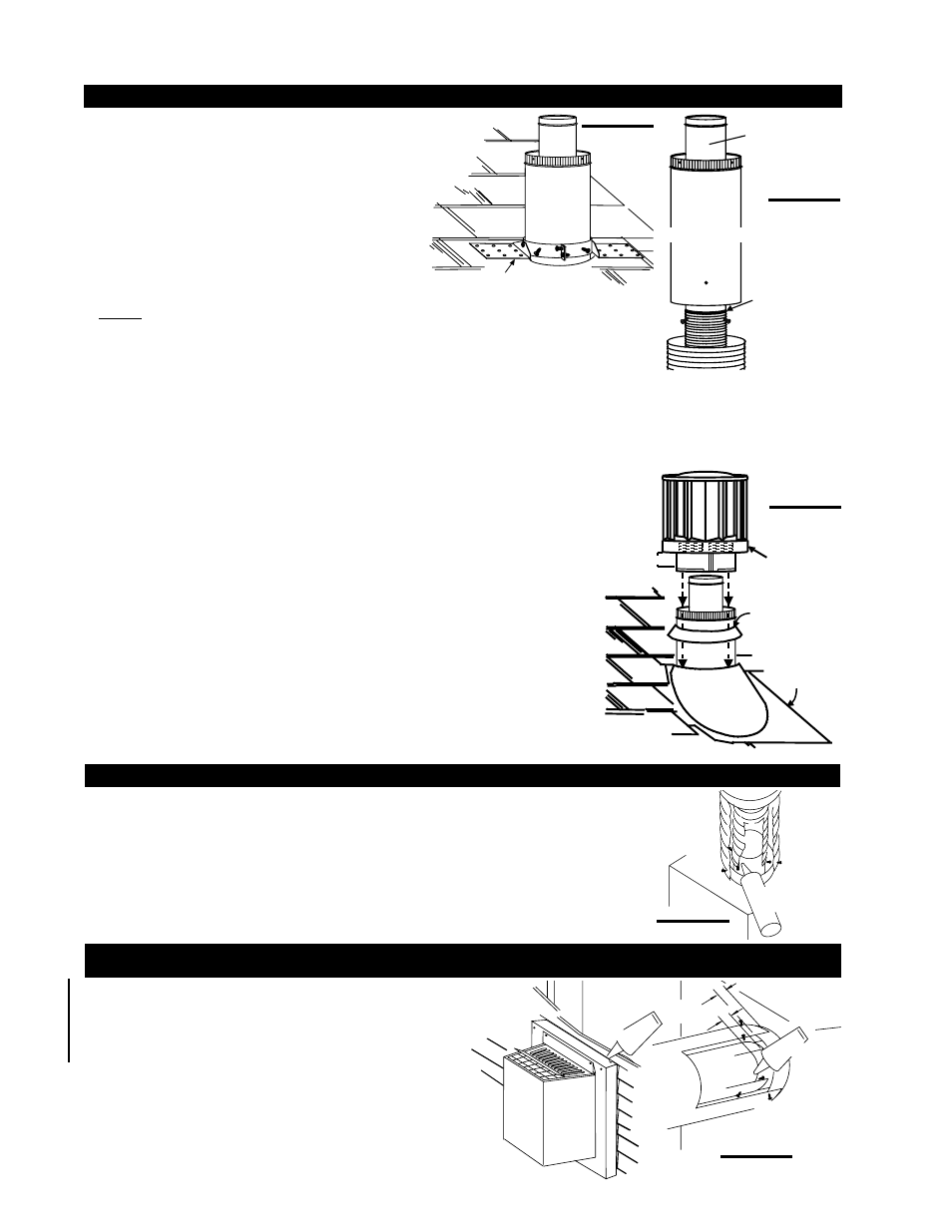
4. Thread the air terminal connector / vent pipe assembly down through the roof. The air terminal must be located vertically
and plumb. Attach the air terminal connector to the roof support, ensuring that the top of the air terminal is 16” above the
highest point that it penetrates the roof. Figure 34. DO NOT CLAMP THE FLEXIBLE VENT PIPE.
5. Remove nails from the shingles, above and to the sides of the chimney. Place the fl ashing over the air terminal connector
leaving a min. 3/4” of the air terminal connector showing above the top of the fl ashing. Slide the fl ashing underneath the sides
and upper edge of the shingles. Ensure that the air terminal connector is properly
centred within the fl ashing, giving a 3/4” margin all around. Fasten to the roof. Do
not nail through the lower portion of the fl ashing. Make weather-tight by sealing
with caulking. Where possible, cover the sides and top edges of the fl ashing with
roofi ng material. Figure 36.
6. Aligning the seams of the terminal and air terminal connector, place the terminal
over the air terminal connector making sure the vent pipe goes into the hole in the
terminal. Secure with the three screws provided. Figure 36.
7. Apply a heavy bead of weatherproof caulking 2" above the fl ashing. Note:
Maintain a minimum 2” space between the air inlet base and the storm collar. Install
the storm collar around the air terminal and slide down to the caulking. Tighten to
ensure that a weather-tight seal between the air terminal and the collar is achieved.
Figure 36.
8. If more vent pipe needs to be used to reach the fi replace, couple them together
as illustrated. The vent system must be supported approximately every 3 feet for
both vertical and horizontal runs. Use noncombustible strapping to maintain the
minimum 1" clearance to combustibles. Figure 33.
ROOF SUPPORT
FIGURE 34
4” FLEXIBLE
VENT PIPE
7” FLEXIBLE
VENT PIPE
INNER
PIPE
HIGH
TEMPERATURE
SEALANT
AIR
TERMINAL
CONNECTOR
FIGURE 35
VERTICAL AIR TERMINAL INSTALLATION
1. Install the 4" fl exible vent pipe to the fi replace. Secure with 3 screws and fl at washers. Seal
the joint and screw holes using the high temperature sealant W573-0007 (not supplied).
2. Install the 7" fl exible vent pipe to the fi replace. Attach and seal the joints using the high
temperature sealant W573-0002 (not supplied).
FIREPLACE VENT CONNECTION
FIGURE 36
USING RIGID VENT COMPONENTS
The vent system must be supported approximately every 3 feet
for both vertical and horizontal runs. Use Napoleon® support
ring assembly W010-0370 or equivalent noncombustible
strapping to maintain the minimum clearance to combustibles
for both vertical and horizontal runs.
SCREWS
#10x2"
7"RIGID
VENT
PIPE
CAULKING
4"RIGID
VENT
PIPE
SCREWS
SELF DRILLING
#8x1/2"
1"OVERLAP
SEALANT
HI-TEMP
ATTENTION-CHAUD
CAUTION -
HOT
FIGURE 38
STORM
COLLAR
FLASHING
CAULKING
WEATHER
SEALANT
2”
AIR INLET
BASE