Vertical installation – Napoleon Fireplaces GD36PTR User Manual
Page 18
18
W415-0210 / R / 02.27.08
This application occurs when venting through a roof. Installation kits for various roof pitches are available from your Napoleon®
dealer. See Accessories to order the specifi c kit required.
1. Determine the air terminal location, cut and frame a 9½" square opening in the ceiling and the roof
to provide the minimum clearance between the vent pipe and any combustible material. Try to center
the vent pipe location midway between two joists to prevent having to cut them. Use a plumb bob to
line up the center of the openings.
Do not fi ll this space with any type of material.
A vent pipe shield will prevent any materials such as insulation, from fi lling
up the 1" air space around the pipe. Nail headers between the joist for extra
support.
2. Apply a bead of caulking (not supplied) to the framework or to the Wolf
Steel vent pipe shield plate or equivalent (in the case of a fi nished ceiling), and secure over the
opening in the ceiling. A fi restop must be placed on the bottom of each framed opening in a roof
or ceiling that the venting system passes through. Apply a bead of caulking all around and place a
fi restop spacer over the vent shield to restrict cold air from being drawn into the room or around the
fi replace. Ensure that both spacer and shield maintain the required clearance to combustibles. Once
the vent pipe is installed in its fi nal position, apply sealant
between the pipe and the fi restop assembly.
3. In the attic, slide the vent pipe collar down to cover
up the open end of the shield and tighten. This will prevent
any materials, such as insulation, from fi lling up the 1" air
space around the pipe.
VERTICAL INSTALLATION
FIGURE 29
FIGURE 28
FIRESTOP
UNDERSIDE OF JOIST
9
1
/
2
”
9
1
/
2
”
SHIELD
FIGURE 30
VENT
PIPE
COLLAR
VENT PIPE
SHIELD
CAULKING
VENT PIPE
SHIELD
FIGURE 27
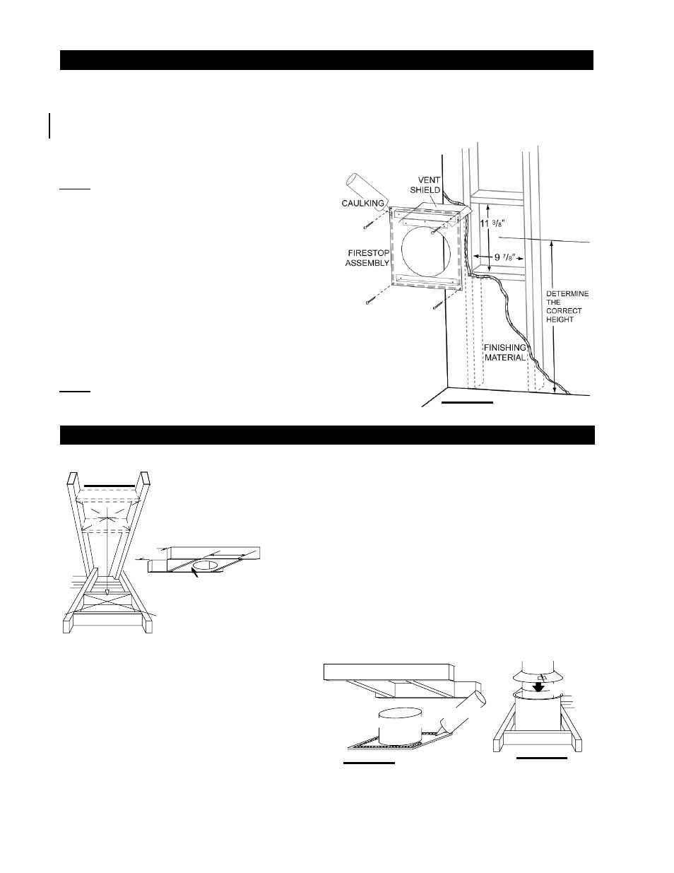
BGD36 FIRESTOP ASSEMBLY
Having determined the correct height for the air terminal location, cut and frame a hole in the exterior wall 9 7/8" wide by 11
3/8" high to accommodate the fi restop assembly. Dry fi t the fi restop assembly before proceeding to ensure the brackets on
the rear surface fi t within the horizontal framing.
The fi restop spacer and shield do not limit the thickness of a wall. For wall construction when using less than 2" x 6" framing
the shield must be cut to suit.
As an alternative to framing, the vent pipe/liner can be enclosed in the wall using
Napoleon® vent sleeve VS47KT.
NOTE: THE FIRESTOP ASSEMBLY MUST BE
INSTALLED WITH THE VENT SHIELD TO THE TOP.
The length of the vent shield may be cut shorter for
combustible walls that are less than 8 1/2" thick but in
these cases the vent shield must extend the full depth of
the combustible wall.
1. Apply a bead of caulking (not supplied) around the
outer edge of the inside surface of the fi restop assembly,
fi t the fi restop assembly to the hole and secure using the
4 screws W570-0026 (supplied in your manual baggie).
2. Once the vent pipe liner is installed in its fi nal position, apply high temperature
sealant W573-0002 (not supplied) between the pipe / liner, and the fi restop.
This restricts cold air from being drawn into the room or around the fi replace.
NOTE: DO NOT FILL THE CAVITY BETWEEN THE PIPE / LINER, FIRESTOP
SLEEVE, AND THE FRAME WITH ANY TYPE OF MATERIAL.