Pin functions, Port pins – NEC PD75P308 User Manual
Page 5
µ
PD75P308
5
E-B
P00
Input
INT4
P01
Input/Output
SCK
P02
Input/Output
SO/SB0
P03
Input/Output
SI/SBI
P10
INT0
P11
INT1
P12
INT2
P13
TI0
P20
PTO0
P21
—
P22
PCL
P23
BUZ
P30*
2
P31*
2
P32*
2
MD2
P33*
2
MD3
P40-43*
2
Input/Output
—
P50-P53*
2
Input/Output
—
P60
KR0
P61
KR1
P62
KR2
P63
KR3
P70
KR4
P71
KR5
P72
KR6
P73
KR7
BP0
S24
BP1
S25
BP2
S26
BP3
S27
BP4
S28
BP5
S29
BP6
S30
BP7
S31
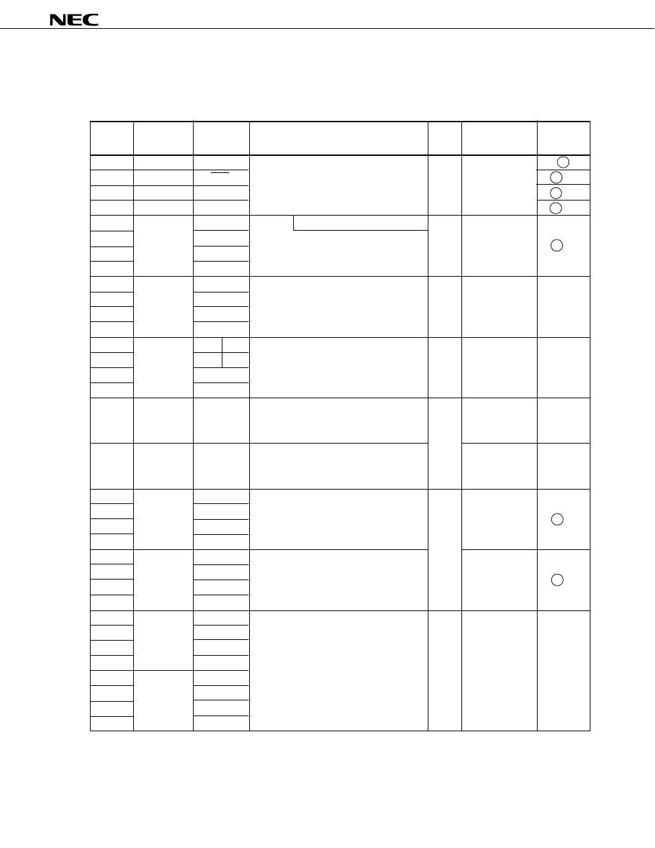
1. PIN FUNCTIONS
1.1 PORT PINS
4-bit input port (PORT0)
Pull-up resistors can be specified in 3-bit
units for the P01 to P03 pins by software.
Input
Input/
Output
Circuit
TYPE
*1
Pin Name Input/Output
Function
8-Bit I/O
When Reset
Also Served
As
F -A
F -B
B
M -C
Input
X
Input
X
4-bit input/output port (PORT2)
Internal pull-up resistors can be
specified in 4-bit units by software.
Input
X
E-B
Input
X
MD0
LCDCL
SYNC MD1
M-A
M-A
●
●
High impedance
High impedance
4-bit input/output port (PORT7)
Internal pull-up resistors can be
specified in 4-bit units by software.
●
●
Input
Input
1-bit output port (BIT PORT)
Shared with a segment output pin.
G-C
*3
X
F -A
F -A
Input/Output
Input/Output
Output
Output
Input/Output
Input/Output
With noise elimination function
4-bit input port (PORT1)
Internal pull-up resistors can be
specified in 4-bit units by software.
★
Programmable 4-bit input/output port
(PORT3)
This port can be specified for input/output
in bit units.
Internal pull-up resistors can be
specified in 4-bit units by software.
N-ch open-drain 4-bit input/output port
(PORT4)
Data input/output pin for writing and
verifying of program memory (PROM)
(lower 4 bits)
N-ch open-drain 4-bit input/output port
(PORT5)
Data input/output pin for writing and
verifying of program memory (PROM)
(upper 4 bits)
Programmable 4-bit input/output port
(PORT6)
This port can be specified for input/output
in bit units.
Internal pull-up resistors can be specified
in 4-bit units by software.
*1:
Circles indicate schmitt trigger inputs.
2:
Can directly drive LED.
3:
For BP0-7, V
LC1
indicated below are selected as the input source.
However, the output level is changed depending on BP0-7 and the V
LC1
external circuits.
B -C