NEC PD75P308 User Manual
Page 20
µ
PD75P308
20
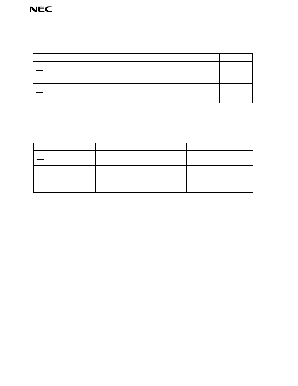
SERIAL TRANSFER OPERATION
TWO-LINE AND THREE-LINE SERIAL I/O MODES (SCK: internal clock output)
Parameter
Symbol
Conditions
MIN.
TYP.
MAX.
Unit
1600
ns
t
KCY1
/2-50
ns
150
ns
400
ns
250
ns
Output
Output
R
L
= 1k
Ω
, C
L
=
100pF*
t
KCY1
t
KH1,
t
KL1
t
SIK1
t
KSI1
t
KSO1
SCK Cycle Time
SCK High-, Low-Level Widths
SI Set-Up Time (vs. SCK )
SI Hold Time (vs. SCK )
SCK SO Output
Delay Time
↑
↑
↓ →
*: R
L
and C
L
are load resistance and load capacitance of the SO output line.
TWO-LINE AND THREE-LINE SERIAL I/O MODES (SCK: external clock input)
*: R
L
and C
L
are load resistance and load capacitance of the SO output line.
Parameter
Symbol
Conditions
MIN.
TYP.
MAX.
Unit
800
ns
400
ns
100
ns
400
ns
300
ns
Input
Input
R
L
= 1k
Ω
, C
L
=
100pF*
t
KCY2
t
KH2,
t
KL2
t
SIK2
t
KSI2
t
KSO2
↑
↓ →
★
★
↑
SCK Cycle Time
SCK High-, Low-Level Widths
SI Set-Up Time (vs. SCK )
SI Hold Time (vs. SCK )
SCK SO Output
Delay Time
- Express 320Lc (4 pages)
- Express5800/120Rh-2 N8100-1125F (406 pages)
- Express NR579-02 (10 pages)
- 140He (360 pages)
- Esmpro EXP350E (2 pages)
- MATWORX NWA-008862-001 (66 pages)
- 1320Xd (20 pages)
- 5020M-16 (149 pages)
- NECCare Standard/300 (11 pages)
- Express 5800/320Lb-R (302 pages)
- Express 5800/320Lc-R (357 pages)
- EXPRESS5800/100 SERIES N8100-1635F (152 pages)
- ExpressA1160 (252 pages)
- EXPRESS 320Lb (39 pages)
- NEAX2000 ND-91649 (58 pages)
- Server Express5800 (400 pages)
- NX7700i/5080H-32 (170 pages)
- EXP351E (2 pages)
- 5800 Series (12 pages)
- Express320F (2 pages)
- 320Fc (120 pages)
- set810 (2 pages)
- NEAX NDA-24349 (421 pages)
- Express5800 Series N8800-090F (358 pages)
- L320 (198 pages)
- Express 456-01721-000 (26 pages)
- INTEL 5800/1000 (12 pages)
- Care Express5800/FT (14 pages)
- Express5800/340Hb-R (4 pages)
- R320A-E4 (23 pages)
- Express 320Fc Systems (10 pages)
- Express 5800/230Eh (342 pages)
- Express N8800-063E/064E (145 pages)
- EXPRESS800 (78 pages)
- MH4500 (186 pages)
- NEAX 2000 IPS (96 pages)
- 2000 (137 pages)
- MC2400 (204 pages)
- Express120Bb-6 (2 pages)
- EXPRESS 320Lb-R (296 pages)
- 120Rf-2 (20 pages)
- A1160 (62 pages)
- 1080Xd (216 pages)