Package drawings – NEC PD75P308 User Manual
Page 28
µ
PD75P308
28
5.
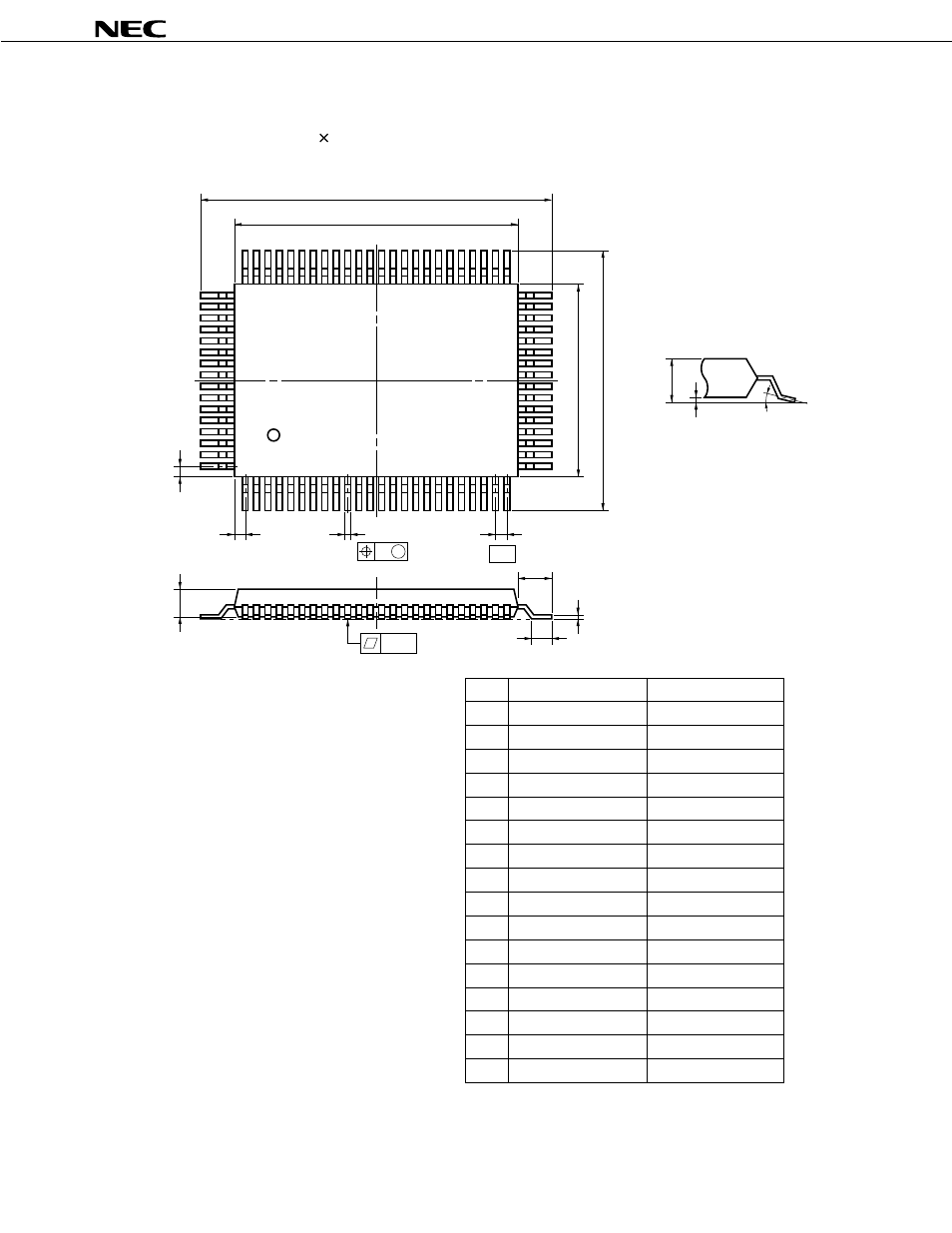
PACKAGE DRAWINGS
N
A
M
F
B
64
65
40
K
L
80 PIN PLASTIC QFP (14
×
20)
80
1
25
24
41
G
D
C
P
detail of lead end
S
Q
5°±5°
M
I
H
J
P80GF-80-3B9-2
ITEM
MILLIMETERS
INCHES
A
B
C
D
F
G
H
I
J
K
L
23.6±0.4
14.0±0.2
0.8
0.35±0.10
0.15
20.0±0.2
0.929±0.016
0.039
0.031
0.006
0.031 (T.P.)
0.795
NOTE
M
N
0.15
0.15
1.8±0.2
0.8 (T.P.)
0.006
0.006
+0.004
–0.003
Each lead centerline is located within 0.15
mm (0.006 inch) of its true position (T.P.) at
maximum material condition.
0.071
0.014
0.551
0.8±0.2
0.031
P
2.7
0.106
0.693±0.016
17.6±0.4
1.0
+0.009
–0.008
Q
0.1±0.1
0.004±0.004
S
3.0 MAX.
0.119 MAX.
+0.10
–0.05
+0.009
–0.008
+0.004
–0.005
+0.009
–0.008
+0.008
–0.009
See also other documents in the category NEC Computers:
- Express 320Lc (4 pages)
- Express5800/120Rh-2 N8100-1125F (406 pages)
- Express NR579-02 (10 pages)
- 140He (360 pages)
- Esmpro EXP350E (2 pages)
- MATWORX NWA-008862-001 (66 pages)
- 1320Xd (20 pages)
- 5020M-16 (149 pages)
- NECCare Standard/300 (11 pages)
- Express 5800/320Lb-R (302 pages)
- Express 5800/320Lc-R (357 pages)
- EXPRESS5800/100 SERIES N8100-1635F (152 pages)
- ExpressA1160 (252 pages)
- EXPRESS 320Lb (39 pages)
- NEAX2000 ND-91649 (58 pages)
- Server Express5800 (400 pages)
- NX7700i/5080H-32 (170 pages)
- EXP351E (2 pages)
- 5800 Series (12 pages)
- Express320F (2 pages)
- 320Fc (120 pages)
- set810 (2 pages)
- NEAX NDA-24349 (421 pages)
- Express5800 Series N8800-090F (358 pages)
- L320 (198 pages)
- Express 456-01721-000 (26 pages)
- INTEL 5800/1000 (12 pages)
- Care Express5800/FT (14 pages)
- Express5800/340Hb-R (4 pages)
- R320A-E4 (23 pages)
- Express 320Fc Systems (10 pages)
- Express 5800/230Eh (342 pages)
- Express N8800-063E/064E (145 pages)
- EXPRESS800 (78 pages)
- MH4500 (186 pages)
- NEAX 2000 IPS (96 pages)
- 2000 (137 pages)
- MC2400 (204 pages)
- Express120Bb-6 (2 pages)
- EXPRESS 320Lb-R (296 pages)
- 120Rf-2 (20 pages)
- A1160 (62 pages)
- 1080Xd (216 pages)