Diskette drive signal cable, Ide signal cables – NEC SP B-Series User Manual
Page 54
3-14 Option Installation
Diskette Drive Signal Cable
A two-connector diskette drive signal cable comes attached to the system board
and to the standard 1.44-MB diskette drive.
Depending on your system, installation of an accessible device, such as a tape
backup unit, may require the replacement of the existing diskette drive signal
cable with a three-connector cable. Connect an optional 5 1/4-inch accessible
device to the middle connector on the three-connector diskette drive signal
cable.
The colored edge of the cable goes to pin 1 on the cable connector. Align the red
edge of the cable with pin 1 (the notched end) on the drive connector.
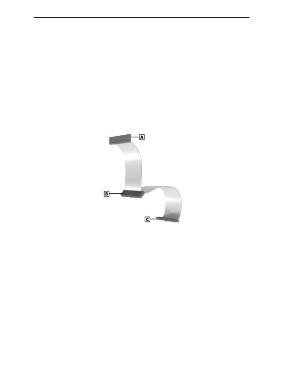
The following figure shows a three-connector diskette drive signal cable.
Diskette Drive Signal Cable
A – Connects to 1.44-MB Diskette Drive
B – Connects to Optional Tape Backup Unit
C – Connects to System Board
IDE Signal Cables
Each system comes with a three-connector IDE interface cable attached to the
primary IDE connector and the installed hard drive. A second IDE cable
connects to the CD-ROM drive and to the secondary IDE connector. In some
systems, a Zip drive also comes attached to the primary IDE cable.
The following figure shows a typical three-connector IDE cable. If the IDE
cable is not keyed with a connector tab, align the colored edge of the cable with
the pin 1 side of the drive connector.