Table b-1. i/o connector signal descriptions, Table b-2. ni 781xr i/o signal summary, Ni 781xr i/o – National Instruments NI 781xR User Manual
Page 36: Signal summary, Can damage, Connecting to compactrio extension i/o chassis
Appendix B
Connecting I/O Signals
B-4
ni.com
end of the cable into the appropriate I/O connector and connect the other
end of the cable to the appropriate signal accessory.
Caution
Connections that exceed any of the maximum ratings of input or output signals
on the NI 781xR can damage the NI 781xR and the computer. Maximum input ratings for
each signal are given in the Protection (Volts) On/Off column of Table B-2. NI is not liable
for any damage resulting from such signal connections.
Connecting to CompactRIO Extension I/O Chassis
You can use the CompactRIO R Series Expansion chassis and CompactRIO
I/O modules with the NI 781xR. Refer to the CompactRIO R Series
Expansion System Installation Instructions for information about
connecting the chassis to the NI 781xR.
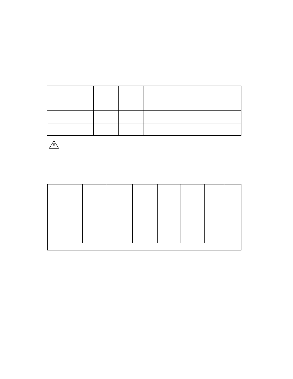
Table B-1. I/O Connector Signal Descriptions
Signal Name
Reference
Direction
Description
+5V
DGND
Output
+5 VDC Source—These pins supply 5 V from the computer
power supply using a self-resetting 1 A fuse. No more than
250 mA should be pulled from a single pin.
DGND
—
—
Digital Ground—These pins supply the reference for the
digital signals at the I/O connector as well as the 5 V supply.
DIO<0..39>
DGND
Input or
Output
Digital I/O signals.
Table B-2. NI 781xR I/O Signal Summary
Signal Name
Signal
Type and
Direction
Impedance
Input/
Output
Protection
(Volts)
On/Off
Source
(mA at V)
Sink
(mA at V)
Rise
Time
Bias
+5V
DO
—
—
—
—
—
—
DGND
DO
—
—
—
—
—
—
DIO<0..39>
Connector<0..3>
DIO
—
–0.5 to +7.0
5.0 at 2.4
5.0 at 0.4
12 ns
—
DIO = Digital Input/Output
DO = Digital Output