NEC switch User Manual
Page 170
CHAPTER 11 INTERRUPT FUNCTIONS
User’s Manual U12978EJ3V0UD
170
(5) Key return mode register 00 (KRM00)
This register sets the pin that detects a key return signal (rising edge of port 4).
KRM00 is set with a 1-bit an 8-bit memory manipulation instruction.
Bit 0 (KRM000) is set in 4-bit units for the KR00/P40 to KR03/P43 pins. Bits 4 to 7 (KRM004 to KRM007) are
set in 1-bit units for the KR04/P44 to KR07/P47 pins, respectively.
RESET input sets KRM00 to 00H.
Figures 11-6 and 11-7 show the format of key return mode register 00 and the block diagram of the falling edge
detector, respectively.
Figure 11-6. Format of Key Return Mode Register 00
0
1
Key return signal detection selection for P4n/KR0n pin (n = 4 to 7)
No detection
Detection (detecting falling edge of P4n/KR0n)
KRM00n
0
1
Key return signal detection selection for P40/KR00 to P43/KR03 pins
No detection
Detection (detecting falling edge of P40/KR00 to P43/KR03)
KRM000
KRM007 KRM006 KRM005 KRM004
0
0
0
KRM000
KRM00
R/W
FFF5H
00H
R/W
Symbol
Address
After reset
6
5
4
3
2
1
7
0
Cautions
1. Bits 1 to 3 must be set to 0.
2. When the KRM00 register is set to 1, a pull-up resistor is connected automatically.
However, the pull-up resistor is cut for pins in output mode.
3. Before setting KRM00, always set bit 4 of MK0 (KRMK00 = 1) to disable interrupts in
advance. After setting KRM00, clear bit 4 of MK0 (KRMK00 = 0) after clearing bit 4 of
IF0 (KRIF00 = 0) to enable interrupts.
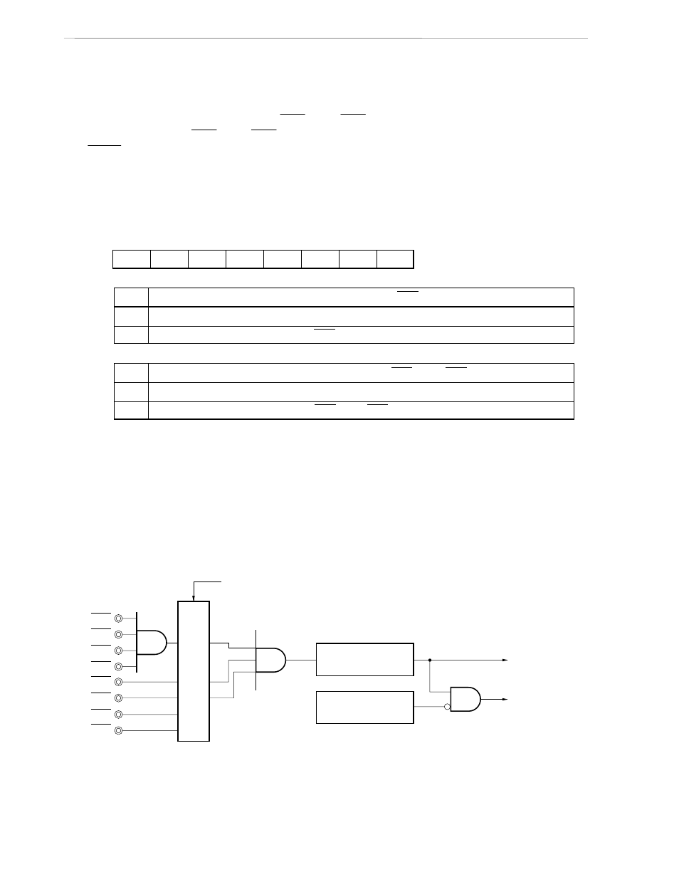
Figure 11-7. Block Diagram of Falling Edge Detector
P40/KR00
P41/KR01
P42/KR02
P43/KR03
P44/KR04
P45/KR05
P46/KR06
P47/KR07
Falling edge detector
KRMK00
KRIF00 set signal
Standby release
signal
Key return mode register 00 (KRM00)
Note
Selector
Note Register that selects the pin used for falling edge input.