Figure 3-1, Faceplate of an optical fibre channel pci adapter, Table 3-2 – NEC 5800/320MA User Manual
Page 61
Hardware Requirements of Optical Fibre Channel PCI Adapters
U525 and U526 Optical Fibre Channel PCI Adapters
3-3
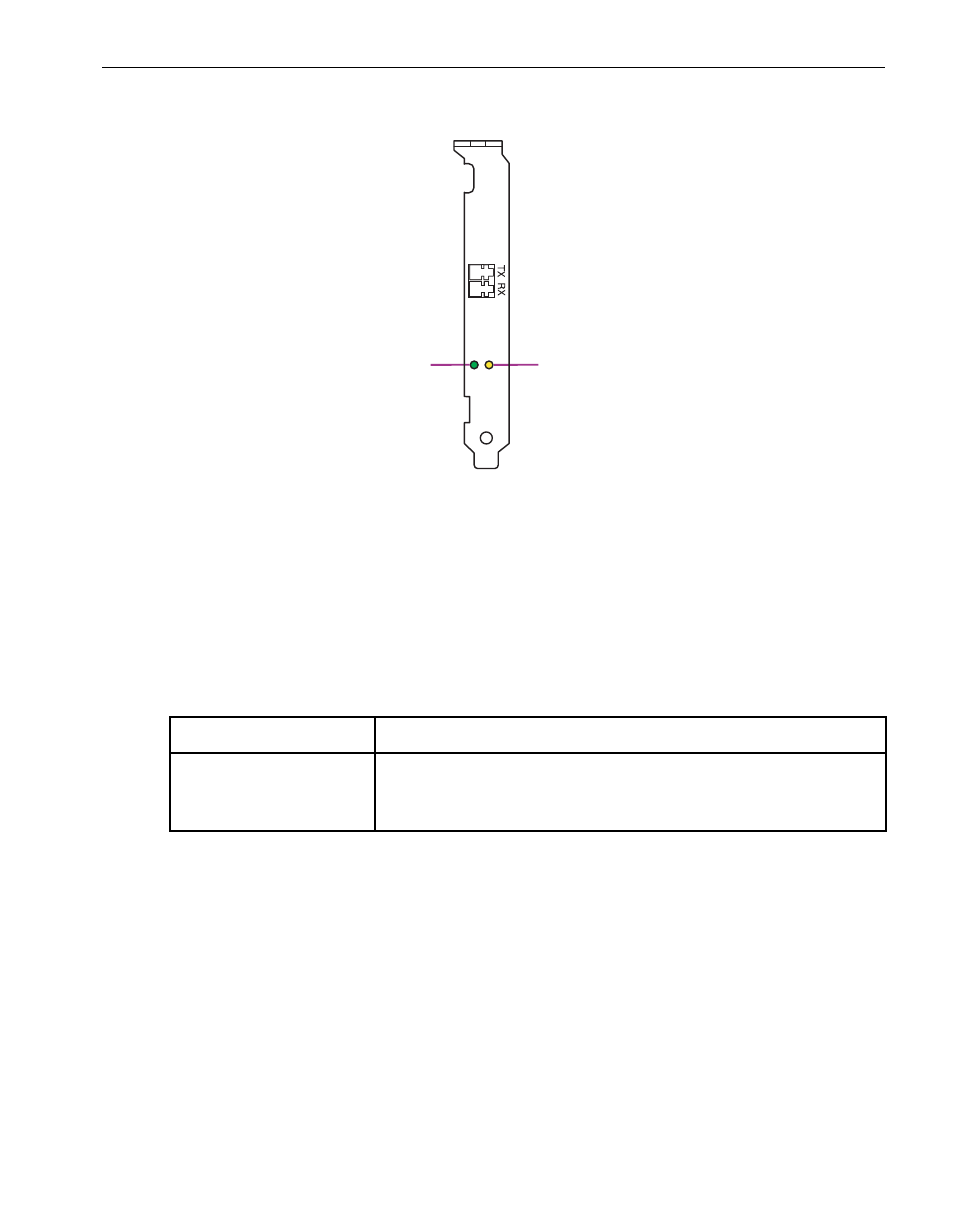
Figure 3-1. Faceplate of an Optical Fibre Channel PCI Adapter
Hardware Requirements of Optical Fibre Channel PCI Adapters
Optical Fibre Channel PCI adapters are optional.
lists the maximum number
of optical Fibre Channel PCI adapters in each system.
You can install full-height PCI adapters only in slot 2 or slot 3. (To provide the
necessary slots in an Express5800/320Ma 3.2 GHz system, you must install the AK533
attachment kit. See the Express5800/320Ma: Operation and Maintenance Guide for
more information.)
Connect two, paired, optical Fibre Channel PCI adapters from each system to a
storage array (for U526 PCI adapters) or to a SAN or switch (for U525 PCI adapters).
Paired PCI adapters occupy paired slots in different enclosures. For example, PCI slots
10/1 and 11/1 are paired slots.
1
Green status LED
2
Amber status LED
Table 3-2. Maximum Numbers of Optical Fibre Channel PCI Adapters
System
Maximum Number of Optical Fibre Channel PCI Adapters
Express5800/320Ma
3.2 GHz and 3.6 GHz,
Dual-Core
2 U525 PCI adapters, part number AA-U52500 or AA-U52510 or
2 U526 PCI adapters, part number AA-U52600 or AA-U52610
mpci082a
FIBRE
CHANNEL
1
2