Mode 2–bidirectional bus – National Instruments PC-DIO-24 User Manual
Page 42
Register-Level Programming
Chapter 4
PC-DIO-24 User Manual
4-12
© National Instruments Corporation
Mode 2–Bidirectional Bus
Mode 2 has an 8-bit bus that can transfer both input and output without changing the
configuration. The data transfers are synchronized with handshaking lines in port C. This mode
uses only port A; however, port B can be used in either mode 0 or mode 1 while port A is
configured for mode 2.
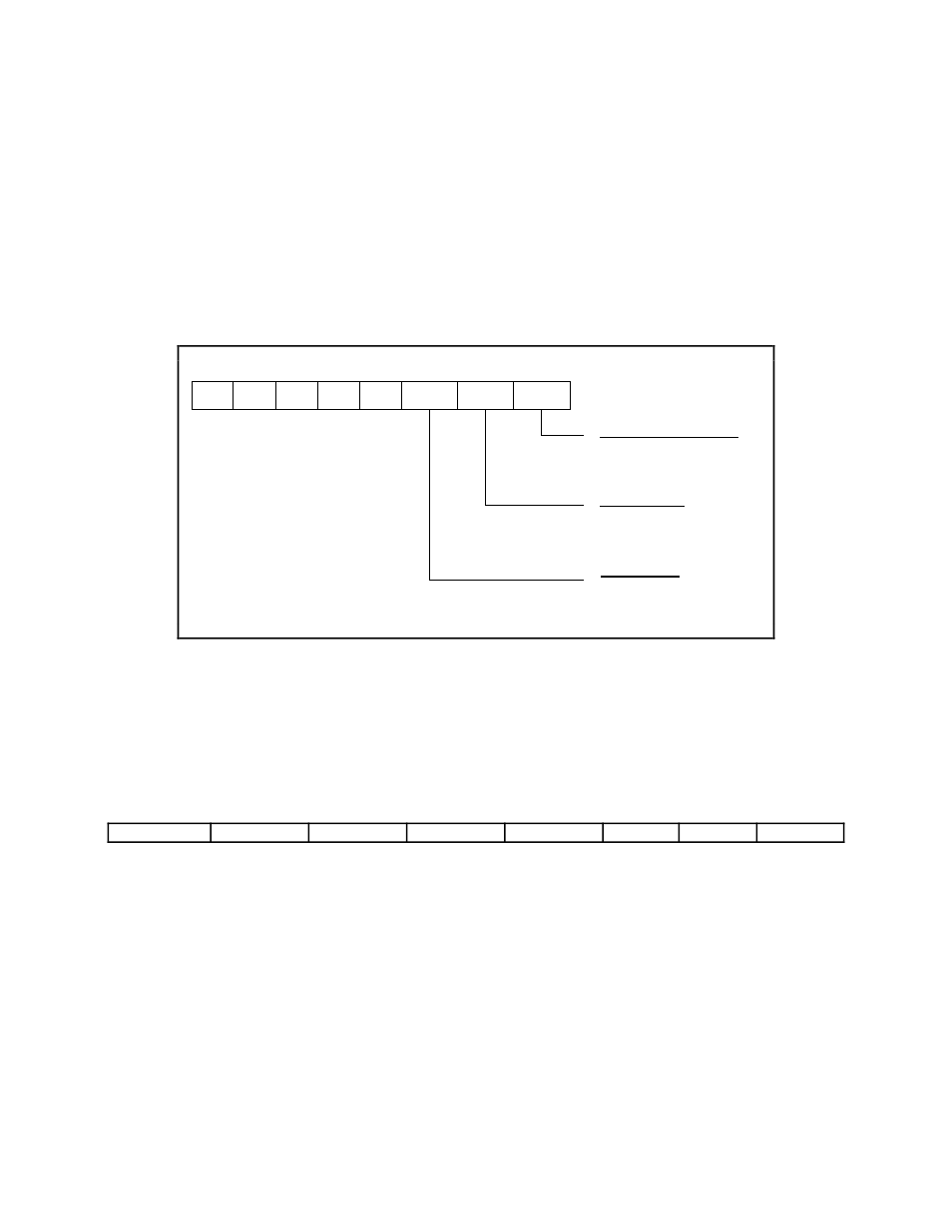
The control word written to the CNFG Register to configure port A as a bidirectional data bus in
mode 2 is shown as follows. If port B is configured for mode 0, then PC2, PC1, and PC0 of
port C can be used as extra input or output lines.
1
1
X
X
X
1/0
1/0
1/0
7
6
5
4
3
2
1
0
1 = input
0 = output
1 = input
0 = output
0 = mode 0
1 = mode 1
Port C bits PC2,PC1,PC0
Port B direction
Group B Mode
During a mode 2 data transfer, the status of the handshaking lines and interrupt signals can be
obtained by reading port C. The port C status-word bit definitions for a mode 2 transfer are
shown as follows.
The following are the port C status-word bit definitions for bidirectional data path (port A only).
7
6
5
4
3
2
1
0
OBFA*
INTE1
IBFA
INTE2
INTRA
I/O
I/O
I/O
Bit
Name
Description
7
OBFA*
Output Buffer Full—Low indicates that the CPU has written data
to port A.
6
INTE1
Interrupt Enable Bit for Output—If this bit is set, interrupts are
enabled from the 82C55A for OBFA*. Controlled by bit set/reset of
PC6.
5
IBFA
Input Buffer Full—High indicates that data has been loaded into
the input latch of port A.
(continues)