Mode 1–strobed output, Mode 1 input programming example – National Instruments PC-DIO-24 User Manual
Page 39
Chapter 4
Register-Level Programming
© National Instruments Corporation
4-9
PC-DIO-24 User Manual
Mode 1 Input Programming Example
Main() {
#define BASE_ADDRESS
0x210
/* Board located at address 210. */
#define PORTAoffset
0x00
/* Offset for port A */
#define PORTBoffset
0x01
/* Offset for port B */
#define PORTCoffset
0x02
/* Offset for port C */
#define CNFGoffset
0x03
/* Offset for CNFG */
register unsigned int porta, portb, portc, cnfg;
char valread;
/* Variable to store data read from a
port */
/* Calculate register addresses. */
porta = BASE_ADDRESS + PORTAoffset;
portb = BASE_ADDRESS + PORTBoffset;
portc = BASE_ADDRESS + PORTCoffset;
cnfg = BASE_ADDRESS + CNFGoffset;
/* EXAMPLE 1–port A input */
outp(cnfg,0xB0);
/* Port A is an input in mode 1. */
while (!(inp(portc) & 0x20));
/* Wait until IBFA is set, indicating that
data has been loaded in port A. */
valread = inp(porta);
/* Read the data from port A. */
/* EXAMPLE 2–port B input */
outp(cnfg,0x86);
/* Port B is an input in mode 1. */
while (!(inp(portc) & 0x02));
/* Wait until IBFB is set, indicating that
data has been loaded in port B. */
valread = inp(portb);
}
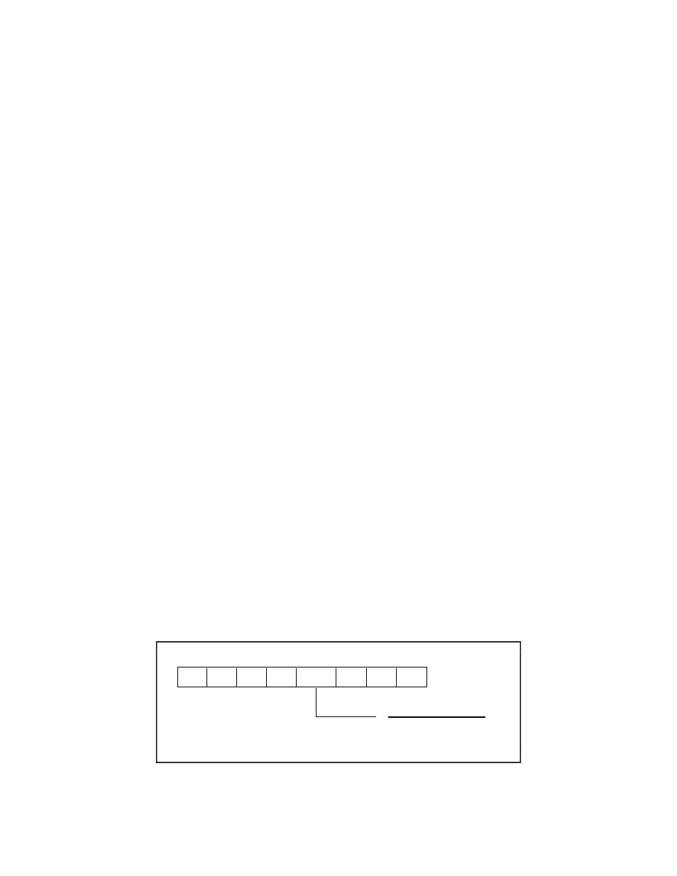
Mode 1–Strobed Output
The control word written to the CNFG Register to configure port A for output in mode 1 is
shown as follows. Bits PC4 and PC5 of port C can be used as extra input or output lines when
port A uses mode 1 output.
1
0
1
0
1/0
X
X
X
7
6
5
4
3
2
1
0
1 = input
0 = output
Port C bits PC4 and PC5