National Instruments PC-DIO-24 User Manual
Page 40
Register-Level Programming
Chapter 4
PC-DIO-24 User Manual
4-10
© National Instruments Corporation
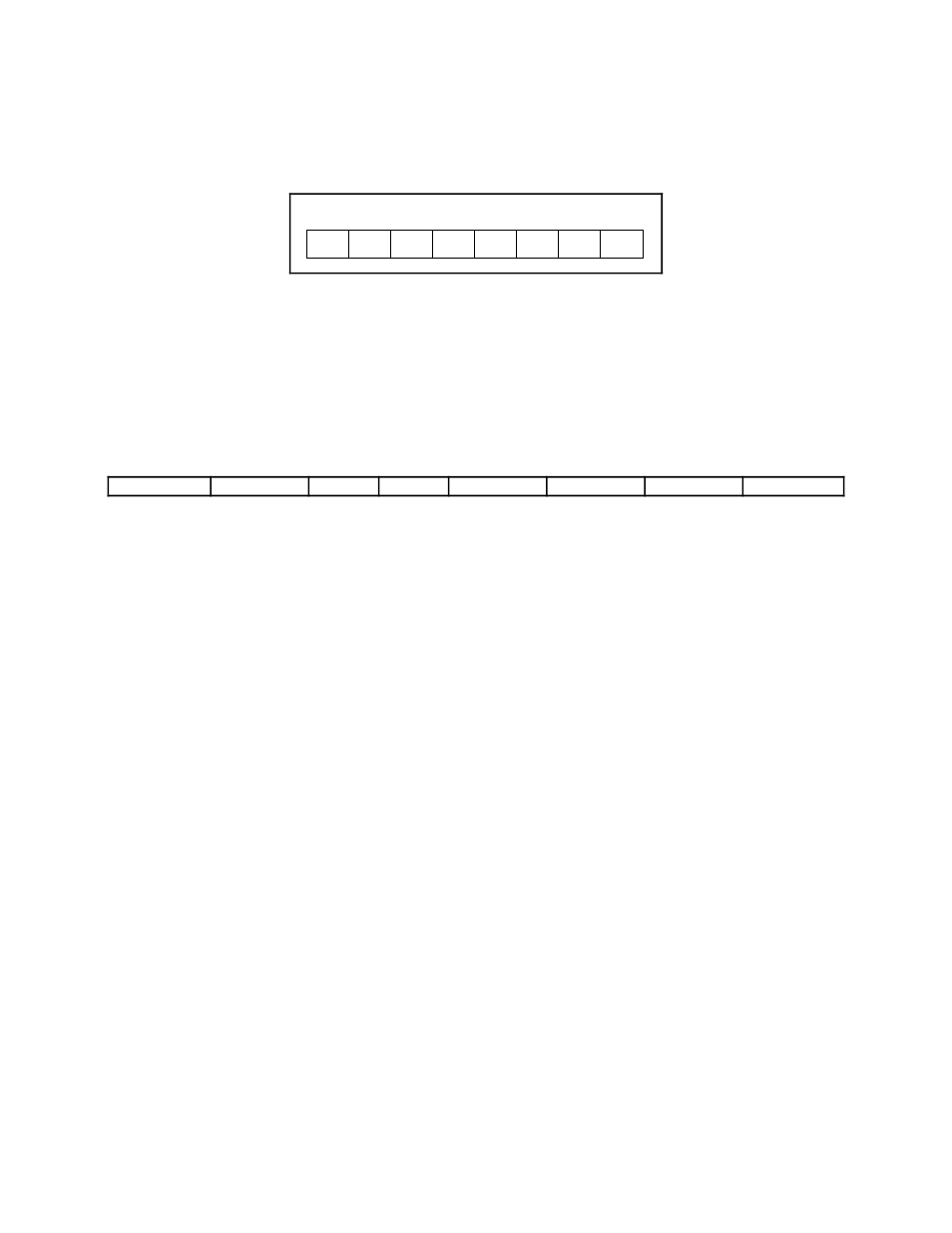
The control word written to the CNFG Register to configure port B for output in mode 1 is
shown as follows. Notice that port B does not have extra input or output lines from port C.
1
X
X
X
X
1
0
X
7
6
5
4
3
2
1
0
During a mode 1 data write transfer, the status of the handshaking lines and interrupt signals can
be obtained by reading port C. Notice that the bit definitions are different for a write and a read
transfer.
The following are the port C status-word bit definitions for output (port A and port B).
7
6
5
4
3
2
1
0
OBFA*
INTEA
I/O
I/O
INTRA
INTEB
OBFB*
INTRB
Bit
Name
Description
7
OBFA*
Output Buffer Full for Port A—Low indicates that the CPU has
written data to port A.
6
INTEA
Interrupt Enable Bit for Port A—If this bit is high, interrupts are
enabled from the 82C55A for port A. Controlled by bit set/reset of
PC6.
5–4
I/O
Input/Output—Extra I/O status line when port A is in mode 1
output.
3
INTRA
Interrupt Request Status for Port A—When INTEA is high and
OBFA* is high, this bit is high, indicating that an interrupt request
is asserted.
2
INTEB
Interrupt Enable Bit for Port B—If this bit is high, interrupts are
enabled from the 82C55A for port B. Controlled by bit set/reset of
PC2.
1
OBFB*
Output Buffer Full for Port B—Low indicates that the CPU has
written data out to port B.
0
INTRB
Interrupt Request Status for Port B—When INTEB is high and
OBFB* is high, this bit is high, indicating that an interrupt request
is asserted.