Signal connections, I/o connector pin description, Figure 2-5. digital i/o connector pin assignments – National Instruments PC-DIO-24 User Manual
Page 23: Figure 2-5, Digital i/o connector pin assignments
Configuration and Installation
Chapter 2
PC-DIO-24 User Manual
2-6
© National Instruments Corporation
Signal Connections
I/O Connector Pin Description
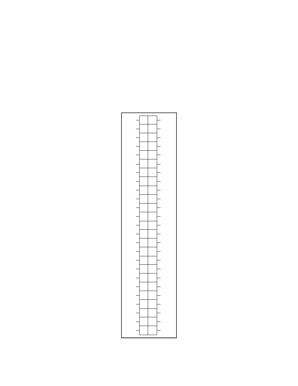
Figure 2-5 shows the pin assignments for the PC-DIO-24 digital I/O connector.
Warning: Connections that exceed any of the maximum ratings of input or output signals on
the PC-DIO-24 may result in damage to the PC-DIO-24 board and to the PC.
Maximum ratings for each signal are given in this chapter under the discussion of
that signal. National Instruments is not liable for any damages resulting from any
such signal connections.
1
2
3
4
5
6
7
8
9
10
11 12
13 14
15 16
17 18
19 20
21 22
23 24
25 26
27 28
29 30
31 32
33 34
35 36
37 38
39 40
41 42
43 44
45 46
47 48
49 50
GND
GND
GND
GND
GND
GND
GND
GND
GND
GND
GND
GND
GND
GND
GND
GND
GND
GND
GND
GND
GND
GND
GND
GND
GND
PC7
PC6
PC5
PC4
PC3
PC2
PC1
PC0
PB7
PB6
PB5
PB4
PB3
PB2
PB1
PB0
PA7
PA6
PA5
PA4
PA3
PA2
PA1
PA0
+5V
Figure 2-5. Digital I/O Connector Pin Assignments