Other timing requirements, Ai convert clock timebase signal, Other timing requirements -27 – National Instruments NI 6232 User Manual
Page 54: Ai convert clock timebase signal -27
Chapter 4
Analog Input
© National Instruments Corporation
4-27
Other Timing Requirements
The sample and conversion level timing of M Series devices work such that
clock signals are gated off unless the proper timing requirements are met.
For example, the device ignores both ai/SampleClock and ai/ConvertClock
until it receives a valid ai/StartTrigger signal. When the device recognizes
an ai/SampleClock pulse, it ignores subsequent ai/SampleClock pulses
until it receives the correct number of ai/ConvertClock pulses.
Similarly, the device ignores all ai/ConvertClock pulses until it recognizes
an ai/SampleClock pulse. When the device receives the correct number of
ai/ConvertClock pulses, it ignores subsequent ai/ConvertClock pulses until
it receives another ai/SampleClock. Figure 4-13 shows timing sequences
for a four-channel acquisition (using AI channels 0, 1, 2, and 3) and
demonstrates proper and improper sequencing of ai/SampleClock and
ai/ConvertClock.
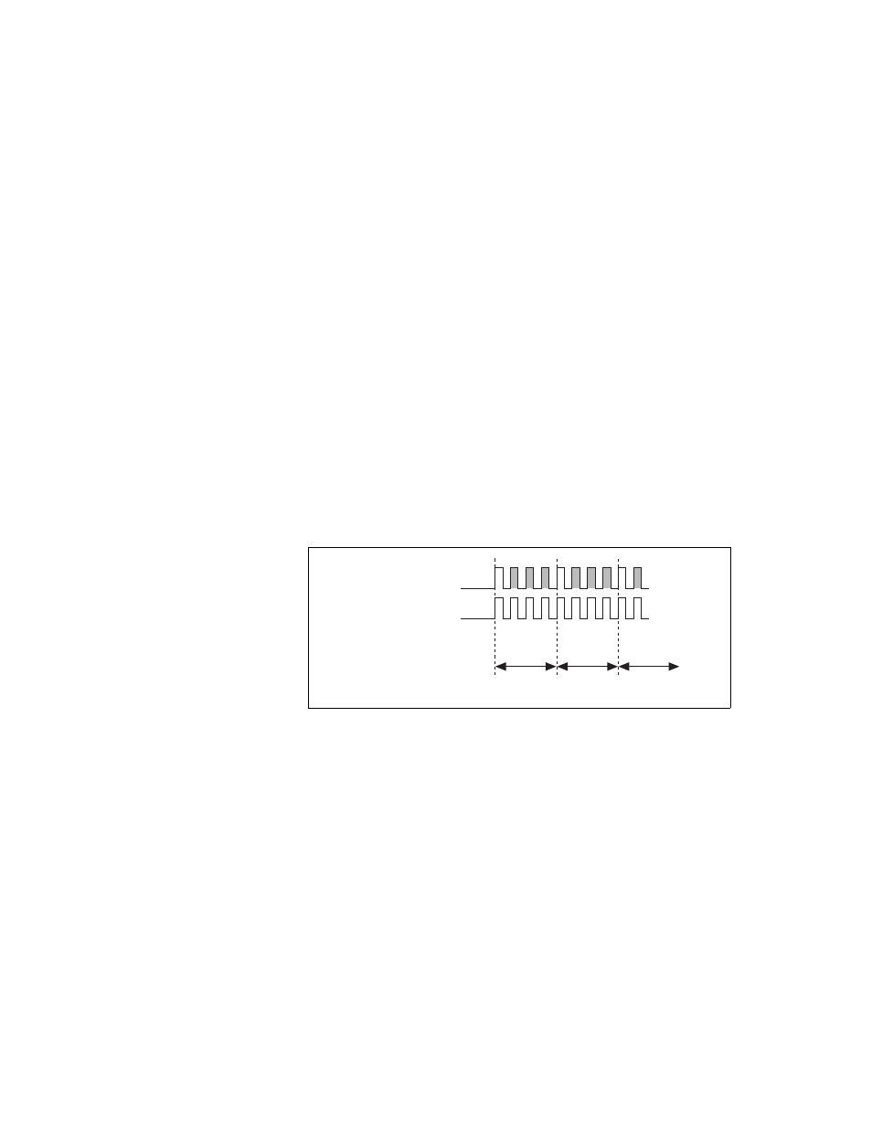
It is also possible to use a single external signal to drive both
ai/SampleClock and ai/ConvertClock at the same time. In this mode, each
tick of the external clock will cause a conversion on the ADC. Figure 4-13
shows this timing relationship.
Figure 4-13. Single External Signal Driving ai/SampleClock and ai/ConvertClock
Simultaneously
AI Convert Clock Timebase Signal
The AI Convert Clock Timebase (ai/ConvertClockTimebase) signal is
divided down to provide on of the possible sources for ai/ConvertClock.
Use one of the following signals as the source of
ai/ConvertClockTimebase:
•
ai/SampleClockTimebase
•
20 MHz Timebase
One External Signal Driving Both Clocks
ai/SampleClock
ai/ConvertClock
Sample #1 Sample #2 Sample #3
1 2 3
0
1 2 3
0 1
…
0
Channel Measured