Pride Mobility jazzy 1120 User Manual
Page 26
26
Jazzy 1120
2000
V I I I . O P E R A T I O N
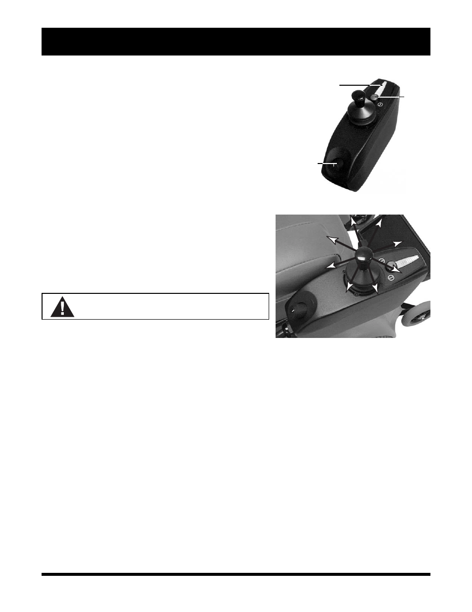
PILOT CONTROLLER
The Pilot controller is an integral controller. See figure 36. This
means that the joystick is housed in the same enclosure as the con-
troller module. This assembly is mounted on the seat arm. The
Pilot controller is connected to the motors, the batteries, and the
battery charger through a cable that connects to the utility tray.
Joystick Functions
The joystick function is similar for all controller configurations. The
joystick controls the direction and speed of the wheelchair. See
figure 37. When you move the joystick from the neutral (center)
position, the electromagnetic brakes release and allow the wheel-
chair to move. The further you push the joystick from its neutral
position, the faster your Jazzy moves. When you release the joy-
stick and allow it to return to the neutral position, you engage the
electromagnetic brakes. This causes the chair to decelerate and
come to a complete stop. If your Jazzy begins to move in an unex-
pected manner, immediately release the joystick. Unless the joy-
stick is damaged, this action should stop your Jazzy.
WARNING! Do not use the on/off key to stop
the chair. This may cause injury.
Speed and Response Adjustment
The Pilot joystick controller is equipped with a speed and response
Figure 37. Joystick Movement
BATTERY
CONDITION
METER
ON/OFF
KEY
SPEED/RESPONSE
ADJUSTMENT
KNOB
Figure 36. Pilot Controller
adjustment knob that allows you to select the speed and response settings best suited to your requirements and environ-
ment. See figure 36. When you increase the speed (clockwise) or decrease the speed (counterclockwise), appropriate
changes are automatically made to the sensitivity.
NOTE: We recommend that the first few times you operate your Jazzy you turn the speed and response
adjustment knob to the slowest setting until you become familiar with your new powered wheelchair.
Battery Condition Meter
The battery condition meter is located immediately in front of the joystick. See figure 36. This enables you to
monitor battery life. The battery condition meter indicates the approximate amount of battery life left.
n Red, yellow, and green bars indicate that the batteries are fully charged.
n Red and yellow bars indicate that you should charge the batteries.
n Red bars indicate that you should charge the batteries as soon as possible, because low battery voltage may
cause your Jazzy to become inoperative.
NOTE: When the batteries approach a discharged state, the first red bar will begin to slowly flash, remind-
ing you the batteries need to be charged immediately!