Aac c m ma aiin nss c co orrd d – Peavey ICS 4200 User Manual
Page 7
7
((7
7)) A
AC
C M
Ma
aiin
ns
s P
Po
ow
we
err R
Re
ecce
ep
ptta
acclle
e
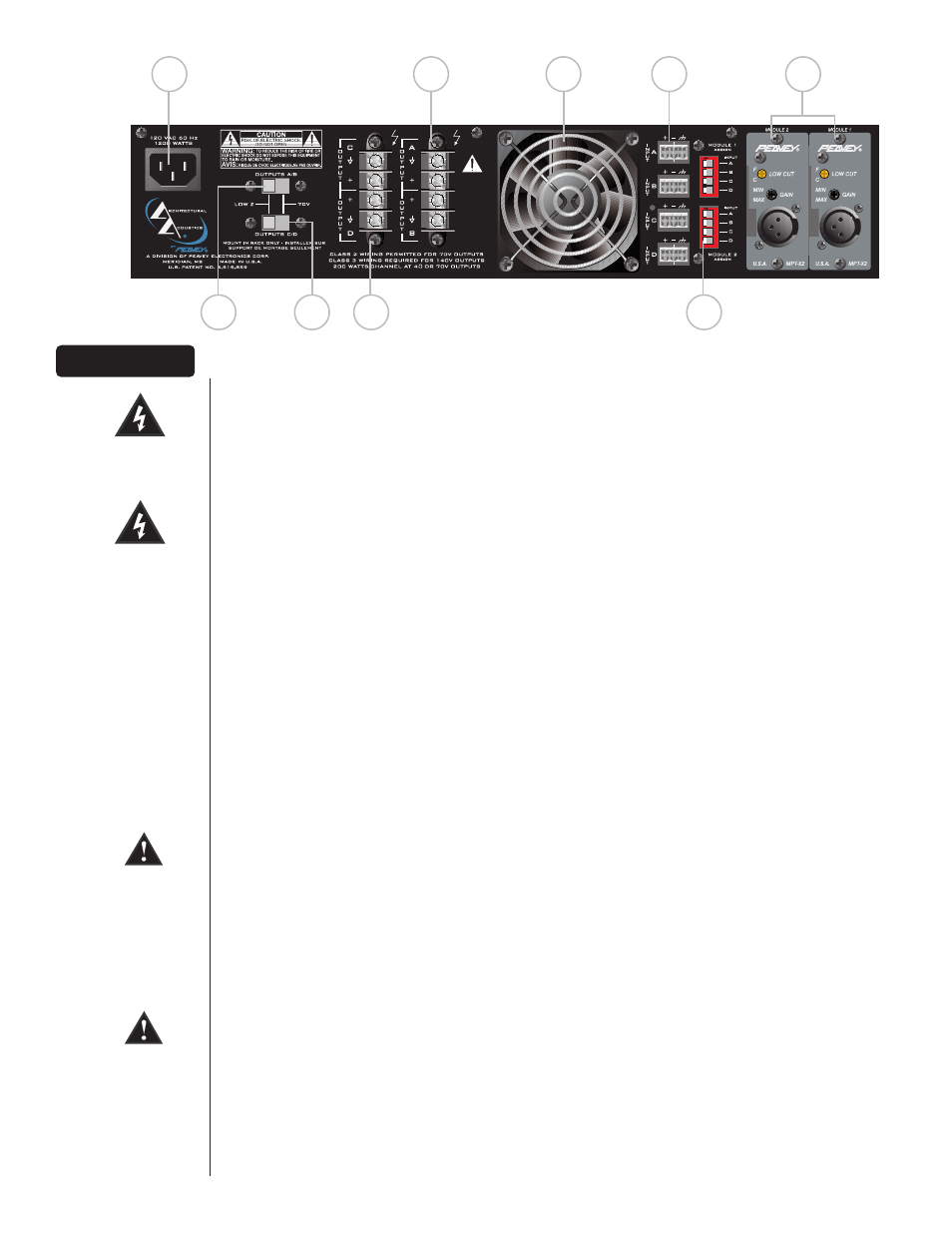
This is a standard IEC power connector. An AC mains cord having the appropriate AC plug and ratings
for the intended operating voltage is included in the carton. The mains cord should be connected to
the amplifier before connecting to a suitable AC outlet.
A
AC
C M
Ma
aiin
nss C
Co
orrd
d
The mains cord supplied with the unit is heavy-duty‚ 3-conductor type with a conventional 120 VAC
plug with ground pin. Never break off the ground pin on any equipment. It is provided for your safety.
If the outlet used does not have a ground pin‚ a suitable grounding adapter should be used and the
third wire should be properly grounded.
((8
8)) C
Ch
ha
an
nn
ne
ell A
A/
/B
B O
Ou
uttp
pu
utt S
Se
elle
ecctto
orr (Low Z or 70 Volt)
This slide switch allows channels A and B of this amp to be configured for either conventional Low Z
or to a 70 Volt distribution loudspeaker system.
((9
9)) C
Ch
ha
an
nn
ne
ell C
C/
/D
D O
Ou
uttp
pu
utt S
Se
elle
ecctto
orr (Low Z or 70 Volt)
This slide switch allows channels C and D of this amp to be configured for either conventional Low Z
or to a 70 Volt distribution loudspeaker system.
((110
0)) C
Ch
ha
an
nn
ne
ell A
A/
/B
B O
Ou
uttp
pu
utts
s
The outputs are screw-terminal type for channels A and B. Connect the loudspeaker system to the
respective positive and ground terminals.
((1111)) C
Ch
ha
an
nn
ne
ell C
C/
/D
D O
Ou
uttp
pu
utts
s
The outputs are screw-terminal type for channels C and D. Connect the loudspeaker system to the
respective positive and ground terminals.
((112
2)) F
Fa
an
n G
Grriillll
A two-speed DC fan supplies cool air to the amplifier. This intake should never be blocked. The fan
automatically switches to high-speed when the unit requires additional cooling. When the amplifier is
relatively cool and at idle‚ the fan should operate at low speed. The fan should never stop unless the
amplifier is switched off or the AC mains power source is interrupted.
((113
3)) C
Ch
ha
an
nn
ne
ell IIn
np
pu
utts
s
These removable “Euro” connectors allow for electronically-balanced input signals to be connected to
the system. Each input has a sensitivity of 1.4 V and low-end roll-off at 60 Hz.
((114
4)) M
MM
MA
A
™
™
P
Pllu
ug
g--iin
n M
Mo
od
du
ulle
e P
Po
orrtts
s
Accepts two optional MMA
™
plug-in input modules. These modules should be selected by installation
requirements. For details‚ refer to the individual MMA Module Operation Guide.
C
Ca
au
uttiio
on
n:: M
MM
MA
A P
Pllu
ug
g--iin
n M
Mo
od
du
ulle
ess ssh
ho
ou
ulld
d n
no
ott b
be
e iin
nsse
errtte
ed
d o
orr rre
em
mo
ov
ve
ed
d w
wh
hiille
e tth
he
e a
am
mp
plliiffiie
err iiss ttu
urrn
ne
ed
d o
on
n..
((115
5)) M
Mo
od
du
ulle
e O
Ou
uttp
pu
utt tto
o C
Ch
ha
an
nn
ne
ell S
Se
elle
ecctto
orrs
s
These DIP switches are used to route the outputs of the respective Module to the desired amplifier
channel(s). For a specific channel selection the DIP switch must be switched.
R
Re
ea
arr P
Pa
an
ne
ell
12
3
4
O
N
12
3
4
O
N
7
10
12
13
14
MODULE 2
MODULE 1
8
9
11
15