Patton electronic 1092ARC User Manual
Page 5
3.1.2
Configuration Switch Set “S1”
The configuration switches on S1 allow you to specify the data
rate, async/sync data format, transmit clock source and response to
RDL request. Default settings of S1 are shown in the table below.
Switches S1-1 and S1-2: Data Rate
Use Switches S1-1 and S1-2
with Switch S5-1 to determine the
operable Sync or Async bit rate for Model 1092ARC. The settings
shown below are the
only applicable bit rate settings.
8
Position
Function
Factory Default
S1-1
Data Rate
On
S1-2
Data Rate
Off
S1-3
DSR during Local Line Loop
On
S1-4
Mangement Setting
Off
S1-5
Reserved
Off
S1-6
Tx Clock Source
On
S1-7
Tx Clock Source
On
S1-8
Respond RDL Request
On
Enable
S1 SUMMARY TABLE
64K Sync
}
}
VT 100 Management
Internal Clock
DSR Enable
S1-1
S1-2
S5-1
Sync Data Rate
Async Data Rate
On
On
Off
32 kbps
Reserved
Off
On
Off
56 kbps
Reserved
On
Off
Off
64 kbps
Reserved
Off
Off
Off
128 kbps
0-38.4 kbps
On
ON
On Reserved for Netlink Management Mode
Off
On
On
Reserved
Reserved
On
Off
On
Reserved
Reserved
Off
Off
On
19.2 kbps
Reserved
Possible Bit Rate Settings -
Switch S1-1, S1-2 and S5-1
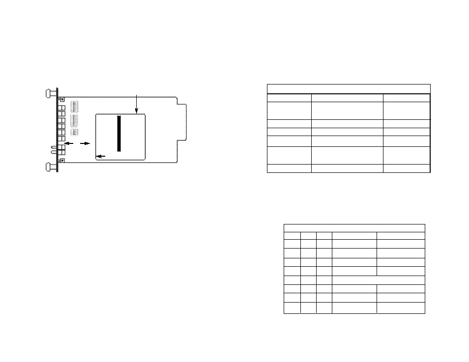
3.1.1 Reversible Interface Driver Board
The Model 1092ARC Series features switchable interface driver
boards that allow a wide range of DTE interface connections. Figure 3
shows the Interface Driver Board on the top of the 1092ARC PC board.
Follow the instructions below to select the correct interface for your
application:
1. With the 1092ARC pulled out of the rack or clusterbox chassis,
locate the driver board on the top of the 1092ARC front card.
2. Lift the interface board gently off of the PC board.
3. Locate the correct interface on the bottom of the driver board.
For example, the RS-232/V.35 interface board is marked
“THIS SIDE UP FOR RS-232” on one side and
“THIS SIDE
UP FOR V.35” on the other side .
4. Re-orient the interface board into the socket with the
appropriate interface pointed UP and with the arrow pointing
toward the front panel of the Model 1092ARC PC board.
5. Push the Interface Driver Board gently onto the socket and re-
install into the rack or cluster system.
7
SW1
SW2
SW5
Interface
Driver
Board
THIS SIDE UP FOR V.35
FRONT
ON OFF
Figure 3. Close up of Model 1092ARC Interface Driver Board