Patton electronic 1092ARC User Manual
Page 13
The table below provides an overview of interface strap functions
for the rear interface cards. Following the table overview are detailed
descriptions of each strap’s function.
DTE Shield (DB-15 Pin 1) & FRGND (JB3)
In the connected position, this strap links DB-15 pin 1 & frame
ground. In the open position, pin 1 is disconnected from frame ground.
JB3
Position 1&2 = DTE Shield (Pin 1) and FRGND Connected
Position 2&3 = DTE Shield (Pin 1) and FRGND Not Connected
Figure 8. 1001RCM11545 strap locations
INTERFACE CARD STRAP SUMMARY TABLE #2
Strap
Function
Position 1&2
Position 2&3
JB3
DTE Shield (Pin1) & FRGND
Connected* Open
JB4
FRGND & SGND (Pin 8)
Connected*
Open
* Indicates default setting
24
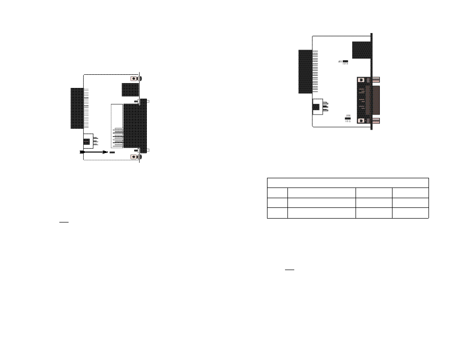
3.3.2 Model 1001RCM13445 Rear Card Strap Settings
Figure 7 shows the strap location for the Model 1001RCM13445
(M/34/RJ-45) rear card. This strap determines whether Signal Ground
and Frame Ground will be connected.
SGND & FRGND (JB4)
In the connected position, this strap links Signal Ground and frame
ground. In the open position, signal ground is disconnected from frame
ground.
JB4
Position 1&2 = SGND and FRGND Connected*
Position 2&3 = SGND and FRGND Not Connected
*
indicates default setting
3.3.3 Model 1001RCM11545 Rear Card Strap Settings
Figure 8 shows strap locations for the Model 1001RCM11545 (DB-
15) rear cards. These straps determine various grounding
characteristics for the terminal interface and twisted pair lines. JB3 and
JB4 are user configurable.
23
Figure 7. M/34/RJ-45 strap locations
JB4
123