Patton electronic 1092ARC User Manual
Page 12
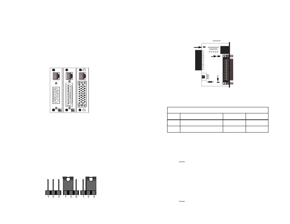
3.3.1 Model 1001RCM12545 Rear Card Strap Settings
Figure 6 shows strap locations for the Model 1001RCM12545
(DB-25/RJ-45S) rear cards. These straps determine various grounding
characteristics for the terminal interface and twisted pair lines. JB3 and
JB4 are user configurable. JB2
must be set on pegs 1 and 2.
The table below provides an overview of interface strap functions
for the rear interface cards. Following the table overview are detailed
descriptions of each strap’s function.
DTE Shield (DB-25 Pin 1) & FRGND (JB3)
In the connected position, this strap links DB-25 pin 1 & frame
ground. In the open position, pin 1 is disconnected from frame ground.
JB3
Position 1&2 = DTE Shield (Pin 1) and FRGND Connected
Position 2&3 = DTE Shield (Pin 1) and FRGND Not Connected
SGND & FRGND (JB4)
In the connected position, this strap links DB-25 pin 7 (Signal
Ground) and frame ground. In the open position, pin 1 is disconnected
from frame ground.
JB4
Position 1&2 = SGND (Pin 7) and FRGND Connected
Position 2&3 = SGND (Pin 7) and FRGND Not Connected
22
Figure 6. DB-25/RJ-45S strap locations
JB3
JB4
JB2
123
123
123
INTERFACE CARD STRAP SUMMARY TABLE #1
Strap
Function
Position 1&2
Position 2&3
JB3
DTE Shield (Pin1) & FRGND
Connected* Open
JB4
FRGND & SGND
Connected*
Open
* Indicates default setting
3.3 CONFIGURE THE REAR INTERFACE CARD
The Model 1092ARC Series has several interface card options: the
Model 1001RCM12545 (DB-25/RJ-45), 1001RCM13445 (M/34/RJ-45),
1001RCM11545 (DB-15/RJ-45), IM2RC/IA, or IM2R/F. Each of these
options supports one DTE interface connection and one 2-Wire/4-Wire
twisted pair line connection. Figure 4 below shows three interface
options. If you are using the IM2RC/IA or IM2RC/F rear cards, refer to
the IM2RC/IA or IM2RC/F manuals for configuration instructions.
Prior to installation, you will need to examine the rear card you
have selected to be sure it is properly configured for your application.
Each rear card is configured by setting straps located on the PC board.
To configure the rear cards, you must set the configuration straps.
Figure 5 below shows the orientation of these straps. Each strap can
either be on pegs 1 and 2, or on pegs 2 and 3. Sections 3.3.1 and
3.3.2 describe the strap locations and possible settings for each rear
card.
21
Figure 4. Model 1092ARC Series interface card options
Figure 5. Orientation of Interface Card Straps
connected
open
M/34 F
DB-25 F
DB-15 F
RJ-45
Model
1001RCM13445
Model
1001RCM11545
RJ-45
RJ-45
Model
1001RCM12545