Multipoint twisted pair connection – Patton electronic 1080A-64 User Manual
Page 20
20
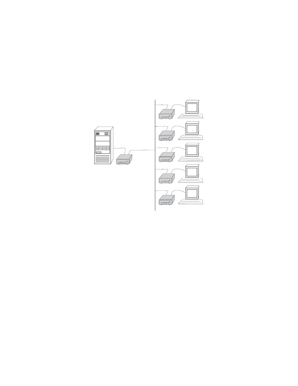
To facilitate multipoint communication, the master Model 1080A should
have its carrier control DIP switch set to “constantly ON” (S1-8=OFF).
Each slave Model 1080A Series unit should have its carrier control DIP
switch set to “controlled by RTS” (S1-8=ON). Figure 5 illustrates a typical
Model 1080A Series multipoint application.
Figure 5.
Typical multipoint set-up
Multipoint Twisted Pair Connection
The Model 1080A Series supports multipoint applications using a star
topology. Maximum distance between the units will vary based upon the
number of drops, data rate, wire gauge, etc. Call Patton Technical Sup-
port for specific distance estimates. The diagrams below show how to
wire the one-pair and two-pair cables properly for a Model star topology.
Note that the ground connection is not needed.