Switch s2-6: v.54 loopback test enable, Switch s2-7: 2-wire/4-wire mode selection, 4 configuration switch set “s3 – Patton electronic 1080A-64 User Manual
Page 12: Switches s3-1 & s3-2: input impedance, Configuration switch set “s3
12
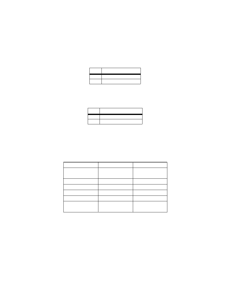
Switch S2-6: V.54 Loopback Test Enable
To reset the V.54 circuit, set switch S2-6 to the “ON” position, then back
to the “OFF” position.
Switch S2-7: 2-Wire/4-Wire Mode Selection
The setting for switch S2-7 determines whether the Model 1080A Series
is operating in 2-wire or 4-wire mode.
3.4 CONFIGURATION SWITCH SET “S3”
The DIP switches on S3 set the anti-stream control, local loopback
enable, remote loopback enable and receive (input) impedance levels for
the Model 1080A Series. Factory default positions of Switch S3 are
shown in Table 4.
Table 4:
S3 Summary
Switches S3-1 & S3-2: Input Impedance
The setting for Switches S3-1 and S3-2 determines the 1080A Series’
input impedance. This allows you to choose the optimum impedance set-
ting for your application. In long distance applications the impedance of
the cable must match the impedance of the load (or resistor) of the
Model 1080A Series unit. Thicker gauge cables requires a lower ohm
S2-6
Setting
Off
V.54 Normal Operation
On
V.54 Testing Disabled
S2-7
Setting
Off
4-wire (full or half duplex)
On
2-wire (half duplex only)
Position
Function
Factory Default
S3-1
Input Impedance
On
S3-2
Input Impedance
Off
S3-3
Not yet assigned
n/a
S3-4
Mode Selection
On Point to Point
S3-5
Local Loopback
Off
Disabled
S3-6
Remote Loopback
Off
Disabled
S3-7
Anti-stream Control
Off
S3-8
Anti-stream Control
Off
200 Ohms
Disabled
}
}