2-3 output sel, 2-4 video out setting, Output sel – Panasonic AJ-HDX900E User Manual
Page 103: Video out setting, Chapter 7 menu description tables, Continued)
103
7
Chapter 7 Menu description tables
(continued)
The underlining in the variable range column indicates the setting in the preset
mode.
7-2-3 OUTPUT SEL
C U F
C U F
C U F
C U F
Item
Variable
range
Remarks
OUTPUT ITEM
MENU
ONLY
TC
STATUS
For setting the characters superimposed on
the output signals from the VIDEO OUT
connector.
MENU ONLY:
The menu screen is superimposed only
when the menu is accessed. This
normally displays nothing.
TC:
Time codes are superimposed (when the
menu is accessed, the menu screen is
superimposed.)
STATUS:
The characters that are the same as the
characters superimposed in the
viewfinder screen are superimposed.
(When the menu is accessed, the menu
screen is superimposed.)
For details, refer to “4-8-1 Settings of signals
output from VIDEO OUT connector.”
MONI OUT
HD-SDI
HD-Y
For setting video signals output from the
MON OUT connector.
HD-SDI:
For outputting the HD SDI signals
HD-Y:
For outputting the analog HD-Y signals
For details, refer to “4-8-2 Settings of signals
output from MON OUT connector.”
MONI OUT CHARA
ON
OFF
For superimposing characters on the HD
SDI output signals from the MON OUT
connector.
ON: To superimpose
OFF: Not to superimpose
CHARACTER switch.
MONI OUT MODE
CAM
VTR
For switching the signals output from the
MON OUT connector.
CAM: The camera images are output at all
times.
VTR: In the recording or other EE mode,
camera images are output from the
connector; in playback mode, the
VTR’s playback signals are output.
C U F
VF MODE
CAM
VTR
For switching the display mode of the
viewfinder screen.
CAM: The camera images are output at all
times.
VTR: In the recording or other EE mode,
camera images are displayed; in
playback mode, the VTR’s playback
images are displayed.
C U F R
C U F R
C U F R
C U F R
C U F R
C U F R
C U F R
C U F R
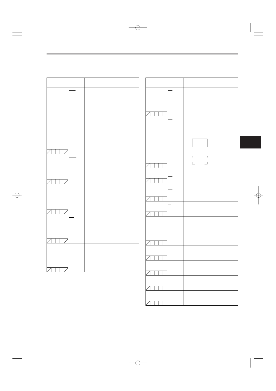
USER BOX WIDTH
1
:
13
:
100
For setting the horizontal width of the user
box.
USER BOX
HEIGHT
1
:
13
:
100
For setting the vertical height of the user
box.
USER BOX H POS
–50
:
+00
:
+50
For setting the horizontal position of the user
box center.
USER BOX V POS
–50
:
+00
:
+50
For setting the vertical position of the user
box center.
Item
Variable
range
Remarks
VIDEO OUT
CENTR MARK
OFF
1
2
3
4
For setting the center marker to be
superimposed on the output signals of the
VIDEO OUT connector.
OFF: The center marker is not displayed.
1:
+ (large)
2:
Center blank (large)
3:
+ (small)
4:
Center blank (small)
VIDEO OUT
SAFETY MARK
OFF
1
2
For setting the type of safety marker frame
to be superimposed on the output signals of
the VIDEO OUT connector.
OFF: The safety marker frame is not
displayed.
1:
Box
2:
Corner frames
VIDEO OUT FRM
MARK
ON
OFF
For superimposing the frame marker on the
output signals from the VIDEO OUT
connector.
ON: To superimpose
OFF: Not to superimpose
VIDEO OUT USER
BOX
ON
OFF
For superimposing the user box on the
output signals from the VIDEO OUT
connector.
ON: To superimpose
OFF: Not to superimpose
O
It is not superimposed when the VIDEO
OUT switch is set to the SD-SDI or VBS
position.
7-2-4 VIDEO OUT SETTING
SAFETY AREA
80%
:
90%
:
100%
For setting the size of the safety marker.
It is possible to set the size by units of 1%
with a fixed ratio between of width and
height.
C U F R
C U F R
FRM SIG
4:3
13:9
14:9
VISTA
For setting the frame marker.
The VISTA setting is 16:8.65.
O
The user box can be displayed in any position as a box-
type cursor.
O
When the DOWNCON MODE item on the DOWNCON
SETTING screen is set to LT-BOX or S-CROP, the frame
marker and the safety marker are not displayed.