Panasonic KX-FT21RS User Manual
Page 124
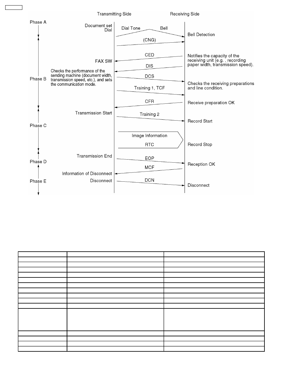
Explanation of Signals
Control signals are comprised mainly of 8-bit identification signals and of the data signals added to them. Data signals are
added to DIS and DCS signals.
Signal.....DIS (Digital Identification Signal)
Identification Signal Format.....00000001
Function:
Notifies the capacity of the receiving unit. The added data signals are as follows.
(Example)
Bit No.
DIS/DTC
DCS
1
Transmitter - T.2 operation
2
Receiver - T.2 operation
Receiver - T.2 operation
3
T.2 IOC = 176
T.2 IOC = 176
4
Transmitter - T.3 operation
5
Receiver - T.3 operation
Receiver - T.3 operation
6
Reserved for future T.3 operation features.
7
Reserved for future T.3 operation features.
8
Reserved for future T.3 operation features.
9
Transmitter - T.4 operation
10
Receiver - T.4 operation
Receiver - T.4 operation
11, 12
(0, 0)
(0, 1)
(1, 0)
(1, 1)
Data signaling rate
V.27 ter fall back mode
V.27 ter
V.29
V.27 ter and V.29
Data signaling rate
2400 bit/s, V.27 ter
4800 bit/s, V.27 ter
9600 bit/s, V.29
7200 bit/s, V.29
13
Reserved for the new modulation system.
14
Reserved for the new modulation system.
15
Vertical resolution = 7.7 line/mm
Vertical resolution = 7.7 line/mm
16
Two-dimensional coding capability
Two-dimensional coding
124
KX-FT21RS