Comsphere 3000 series carrier (rear), Providing power to a co power unit, Information on these powering options, see the – Paradyne COMSPHERE 3600 Series User Manual
Page 26: Providing, Power to a co power unit, Section, Section. t, Section.)
COMSPHERE –48 Vdc Central Office Power Unit
2-10
May 1998
3000-A2-GB41-40
P20
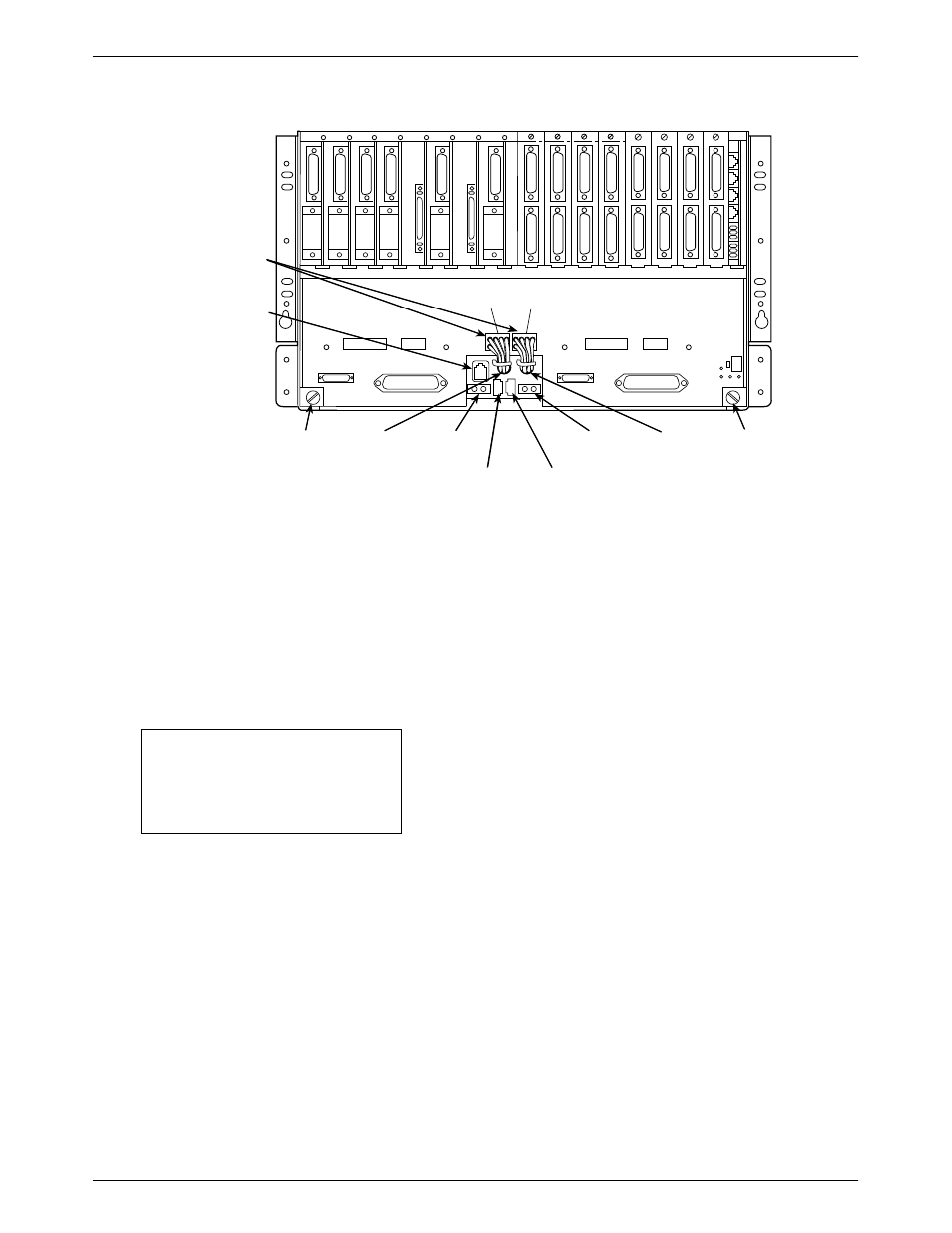
P19
497-13673-01
P3
(OUTPUT)
CAPTIVE
SCREW
P6
(OUTPUT)
–48VDC B
(INPUT)
CAPTIVE
SCREW
BACKPLANE
CONNECTOR
CABLE
ASSEMBLIES
NETWORK
MANAGEMENT
CONNECTOR
ALARM B
ALARM A
–48VDC A
(INPUT)
Figure 2-4. COMSPHERE 3000 Series Carrier (Rear)
Providing Power to a CO Power Unit
After the CO Power Unit installation procedure is
completed, you must provide power to the unit. There are
a number of powering options available depending upon
your configuration.
NOTE
The option strap settings are
factory set for the Basic mode of
operation.
To provide power to the CO Power Unit operating in
Basic mode:
"
Procedure
1. Use one connector housing (AMP part
number 1-480698-0) and two crimp-type contacts
(AMP part number 350550-1) to attach the
connector to your – 48 Vdc power input cable.
Note that you need a hand crimping tool (AMP
part number 90296-2 or equivalent) to build the
connector.
(The contacts are crimp type and are intended for
use with 20 AWG through 14 AWG wire with a
maximum insulation diameter of .130 inches. For
additional information, see
guide.)
2. Provide external fusing, if desired. (The fuse
requirements.) The optional fuse should have a
rating of 6 amperes, 250 volts, and be a fast-acting
type. Use a fuse similar to Littlefuse #312006.
3. Plug the input power cable to either the
– 48VDC A connector or the – 48VDC B
connector. See
settings for this power option are listed in