Pride Mobility Jazzy 1105 User Manual
Page 20
20
www.pridemobility.com
Jazzy 1105/RevH/Feb03
Normally, your Jazzy is shipped fully assembled for your convenience. However, some seatbacks are removed
for shipping purposes. The following is a set of instructions to help you quickly and easily prepare your
Jazzy 1105 for immediate use. You will need a Phillips head screwdriver and a 3/16-in. hex wrench.
PARTS LIST
QUANTITY
Phillips Head seatback mounting screws
4
Seatback
1
8-in. wire ties
1
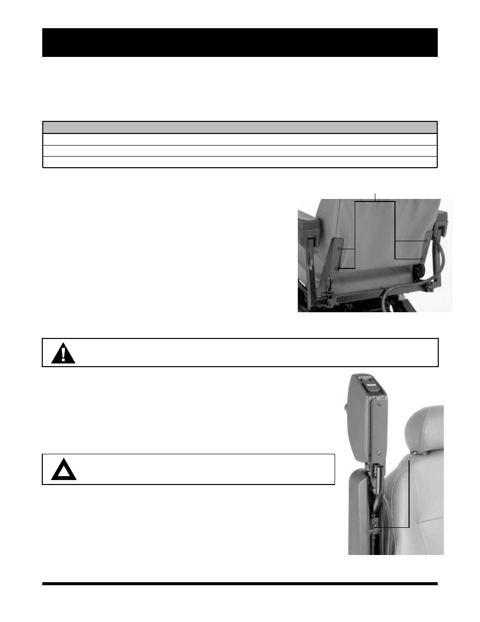
SEATBACK ASSEMBLY
The seatback mounts to the back hinges with four (4) Phillips head
screws.
To mount the seatback to the hinge:
1. Line up the hinges with the holes in the seatback.
2. Insert the seatback mounting screws through the hinge and into
the seatback. See figure 5.
3. Tighten the four screws.
SEAT INSTALLATION
The standard seat installation method incorporates the seat frame
(H-frame) and four (4) adjustable seatposts located on the power
base.
WARNING! Do not pick up the seat frame by the armrests. They are free to pivot, and you may lose
control of the seat if they do so, resulting in personal injury or damage to the chair.
To install the seat:
1. Set seat on the rear seat towers.
2. Push seat back and down until latches engage on the front seat towers.
3. Plug controller cable into the connector on the utility tray.
4. Plug power switch cable (if equipped) into the connector on the utility
tray.
5. Secure the controller cable to the armrest receiver with a wire tie.
CAUTION! Do not place the controller cable so that it can be pinched
in the seat frame or the power base frame.
JOYSTICK INSTALLATION
Your Jazzy may have been shipped without the joystick installed in the armrest.
To install the joystick:
1. Use a 3/16-in. hex wrench to loosen the setscrew. See figure 6.
2. Slide the joystick mounting bracket into or out of the armrest to the desired
position.
3. Retighten the setscrew by it turning clockwise.
V . A S S E M B L Y
Figure 5. Seatback Assembly
SEAT MOUNTING SCREW LOCATIONS
Figure 6. Joystick Installation
JOYSTICK
BRACKET
SETSCREW