1 port j4 pin-outs – Paradise 205486 REV F User Manual
Page 30
30
208495 REV C
Operations Manual, HPA2, Compact Outdoor SSPA
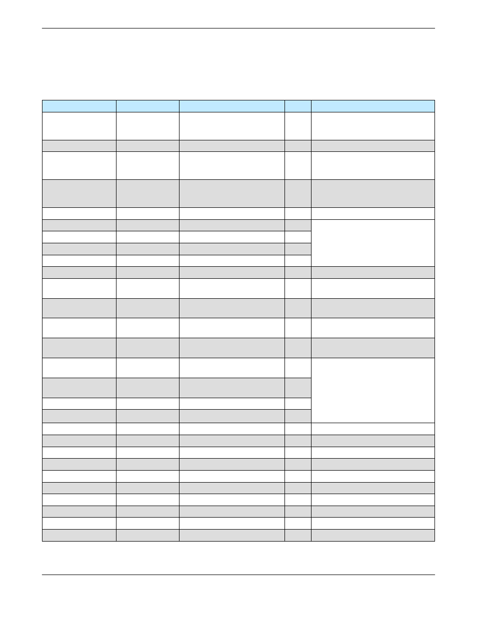
3.1 Port J4 Pin-Outs
Table 3-1 shows the pin-outs for the J4 Monitor & Control Connector for Ethernet capable
units.
Table 3-1: Monitor & Control Connector (J4) Pin-Out (Ethernet capable)
Signal
Type
Function
Pin
Notes
Mute Input
Closure to Ground
Disables DC Power to SSPA
B
Unit powers up muted;
This line must be pulled to ground
(V) to enable amplifier
Auxiliary Input
Closure to Ground
Auxiliary Input
P
Summary Alarm
Form C Relay
Closed on Fault
Common
Open on Fault
L
a
b
L-a : normally open
a-b : normally closed
Auxiliary Alarm
Form C Relay
Closed on Fault
Common
Open on Fault
N
Z
M
N-Z : normally open
Z-M: normally closed
Low RF Fault Output
Open Collector
High on Fault
G
Requires external pull-up
10 Base-T TX-
W
10 Base-T RX-
H
10 Base-T RX+
J
10 Base-T TX+
X
Spare Input
Analog Input
S
+5V max.
RF Power Detector
Analog Output
Relative Indication
of RF Output Power
R
+4.0 VDC at Psat
Gain Adjust Input
Analog Input
Adjusts Amplifier Gain
over 20dB range
A
2.5 vdc = Max Gain 75dB
0.5 vdc = Min Gain 55dB
Block Up Converter
Alarm
Open Collector
High on Fault
f
Requires external pull-up
RS232 / RS485
Select
Closure to Ground Selects Serial Communication
D
Default is RS 485; pull to ground (d)
to enable RS 232
RS 485 TX-
or RS232 OUT
Serial TX Output
Serial Link Data Port
E
Refer to M&C section
RS 485 RX-
or RS232 IN
Serial RX Input
Serial Link Data Port
F
RS 485 TX+
Serial TX Output
Serial Link Data Port
T
RS 485 RX+
Serial RX Input
Serial Link Data Port
U
GND
Signal Ground
Common Signal Return
V
Chassis ground
GND
Signal Ground
Isolated Comm Ground
d
Ground for Signals D, E, & F
Baud Select 0
Closure to Gnd
Select Baud Rate & Protocol
j
Refer to Section 11
Baud Select 1
Closure to Gnd
Select Baud Rate & Protocol
e
Refer to Section 11
PGM Switch
Flash Firmware Port
g
Reserved for Programming
PGM CLK
Flash Firmware Port
c
Reserved for Programming
PGM-Sout
Flash Firmware Port
K
Reserved for Programming
PGM-Sin
Flash Firmware Port
Y
Reserved for Programming
PGM +5V
Flash Firmware Port
h
Reserved for Programming
PGM Enable
Flash Firmware Port
C
Reserved for Programming
Refer to M&C section