Paradise 205486 REV F User Manual
Page 18
18
208495 REV C
Operations Manual, HPA2, Compact Outdoor SSPA
2.2.4 Monitor & Control Connector (J4) [MS3112E18-32S]
The M&C, Monitor and Control, connector is the primary input for controlling the amplifier and
monitoring fault conditions. It is a 32-pin circular connector, MS3112E18-32S. It requires a
mating connector, MS3116F18-32P, which is supplied with the unit. The pin-out for this
connector is described in Section 3, Table 3-2.
2.2.5 Link Port (J5) [MS3112E10-6S]
The interface connector is used to connect between two Compact Outdoor Amplifiers when
used in a 1:1 redundant system. It is a 6 pin circular connector, MS3112E10-6S. It requires a
mating connector, MS3116F10-6P. A link cable is provided with a 1:1 Redundancy Kit which
can be purchased separately. See Table 2-1.
2.2.6 Switch Port (J6) [MS3112E10-6S]
When used in a 1:1 redundant system, the waveguide switch must be connected to the switch
port of each amplifier (MS3112E10-6S). See Table 2-2. It mates with MS3116F10-6P.
2.2.7 Prime Power Connection (J7) [MS3102E20-3P]
The AC Input connector, J7, is located on the bottom side of the Compact Outdoor Amplifier
package (see Figure 2-4). There are also two alternate placements for this connector on the
RF Output end of the amplifier as shown in Figure 2-3. This connector is a 3-pin circular
connector, MS3102E20-3P. The mating connector (MS3106E20-3S) is shipped with the unit.
The pin out for this connector is given in Table 2-3.
WARNING! Always terminate the RF input and output connectors prior to
applying prime AC input power!
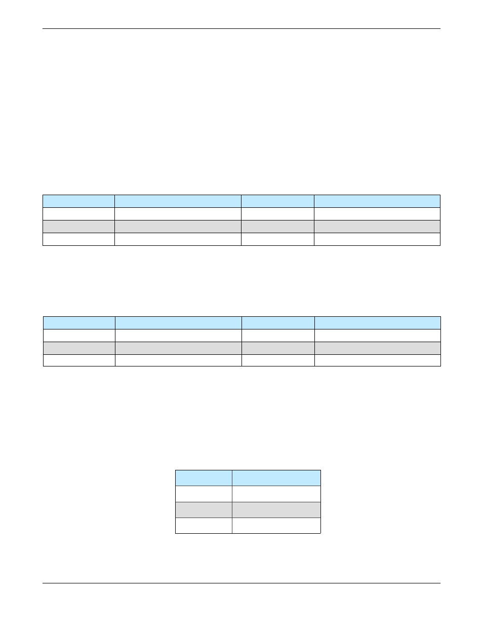
Table 2-1: Link Port (J5) Pin-Outs
Pin # on J5
Connection
Pin # on J5
Connection
A LINK
OUT D
N/C
B
LINK IN
E
N/C
C N/C F GND
Table 2-2 Switch Port (J6) Pin-Outs
Pin # on J6
Connection
Pin # on J6
Connection
A N/C D N/C
B
N/C
E
POS 2
C
+28 VDC
F
POS 1
Pin # on J7
Connection
A L1
B
GND
C L2/N
Table 2-3: AC Line Input Connector