Installing the router, Smartlink 4020 installation diagram – Patton electronic 4020 Series User Manual
Page 23
Installing the router
23
SmartLink 4020 Getting Started Guide
2 • SmartLink installation
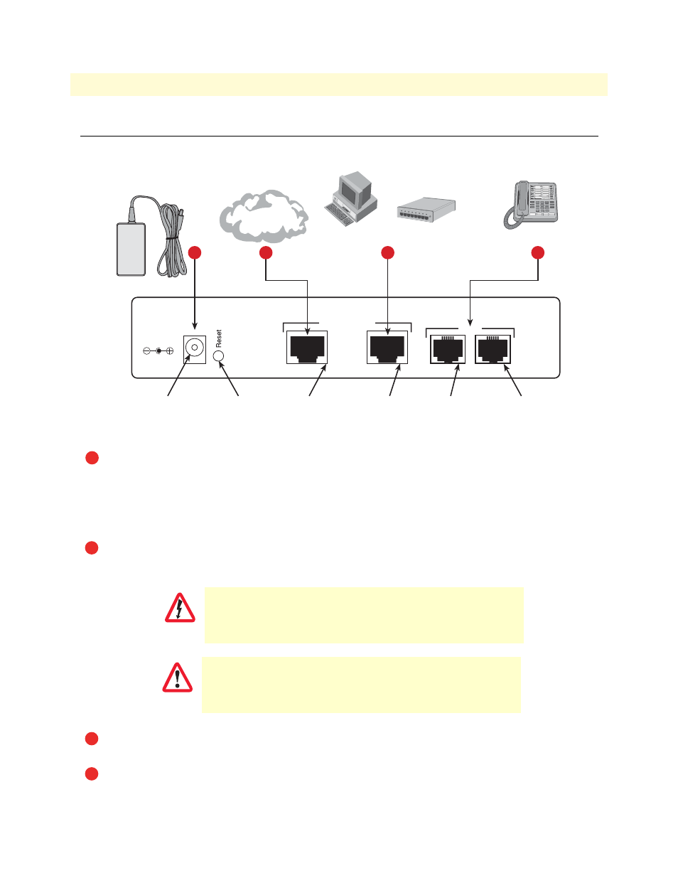
Installing the router
Do the following:
Figure 2.
SmartLink 4020
installation diagram
Note
For proper ventilation, leave at least 2 inches (5 cm) of clearance at the sides,
front, and rear of the unit.
Place the unit on a desktop or similar sturdy, flat surface that offers easy access to the cables. The unit
should be installed in a dry environment with sufficient space to allow air circulation for cooling.
Set your LAN Local Area Connection Properties for Internet Protocol (TCP/IP) to Obtain an IP address
automatically and to Obtain DNS server address automatically.
Do not work on the system or connect or disconnect cables during periods of
lightning activity.
The Interconnecting cables shall be acceptable for external use
and shall be rated for the proper application with respect to volt-
age, current, anticipated temperature, flammability, and mechani-
cal serviceability
Plug in the telephone or telephones (see
Plug in the PC or LAN, or a LAN hub/switch.
12V, 1A
Power
www.patton.com
WAN
LAN
10/100 Ethernet
Phone
1
2
Power jack
WAN port
LAN port
Phone jack 1
Phone jack 2
Reset button
6
Power adapter
4
5
PC or
LAN
--or--
LAN
Hub/Switch
Internet Service
Provider
Phone
3
1
2
WARNING
CAUTION
3
4