Figure 27, Figure 28 – ParaBody 425103 User Manual
Page 23
24
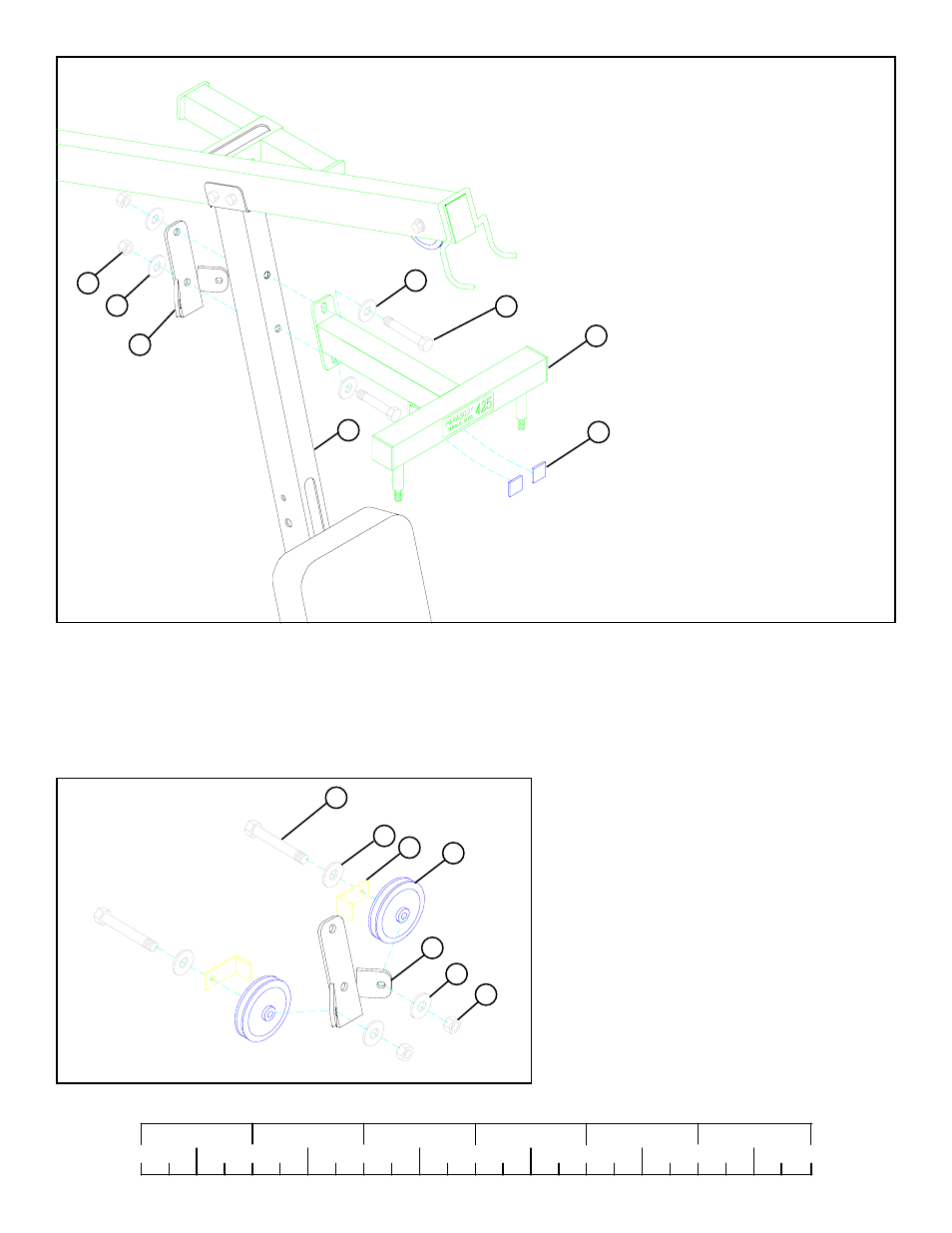
FIGURE 27
STEP 27
0
1
2
3
4
5
6
1/2
1/2
1/2
1/2
1/2
1/2
FIGURE 28
STEP 28
• LOOSELY assemble two 3-1/2” PULLEYS (42) to the
CENTER PULLEY BRACKET (26) using two 3/8 X 2”
BOLTS (84), two 2-3/8” L-BRACKETS (45), four 3/8”
WASHERS (91), and two 3/8” LOCK NUTS (92). See
FIGURE 28.
(NOTE: This connection wil be tightened after the
cable has been routed.)
• SECURELY assemble the BEARING HOUSING (6) and the CENTER PULLEY BRACKET (26) to the FRONT UPRIGHT (25) using two
1/2 X 4-1/2” BOLTS (89) , four 1/2” WASHERS (93), and two 1/2" LOCK NUTS (94). See FIGURE 27.
• Attach two 1 X 1" GUIDES (53) to the ANGLE on the UNDERSIDE of the BEARING HOUSING (6). See FIGURE 27.
94
91
93
26
93
53
25
6
91
92
42
45
26
89 1/2 X 4-1/2”
84 3/8 X 2”
See also other documents in the category ParaBody Sports and recreation:
- Free Weight Systems (5 pages)
- 886101 (3 pages)
- 425/660 (2 pages)
- 822 (9 pages)
- 848101 (14 pages)
- 881 (26 pages)
- Free Weight Smith System (5 pages)
- Leg Press 100101 (14 pages)
- 360101 (11 pages)
- 777 (5 pages)
- 832102 (14 pages)
- Leg Press 100 (11 pages)
- 205101 (1 page)
- 425 (2 pages)
- 440 (33 pages)
- 426103 (45 pages)
- Hip Sled System (24 pages)
- 824 (8 pages)
- GS2 (24 pages)
- 826 (8 pages)
- 856 (6 pages)
- 400101 (27 pages)
- 829 (14 pages)
- 435104 (13 pages)
- GS6 (8 pages)
- 842 (6 pages)
- 778 (13 pages)
- 375101 (22 pages)
- Leg Press 5 (15 pages)
- 838 (10 pages)
- 441101 440 (10 pages)
- LP5 (15 pages)
- Home Guide (9 pages)
- 888 (15 pages)
- cm3 (8 pages)
- 870 (4 pages)
- 893103 (20 pages)
- 890 (10 pages)
- 250101 (18 pages)
- 843 (12 pages)
- GS4 (1 page)
- 849 (7 pages)
- 855 AB (9 pages)
- 883 (31 pages)