Figure 26 – ParaBody 425103 User Manual
Page 22
23
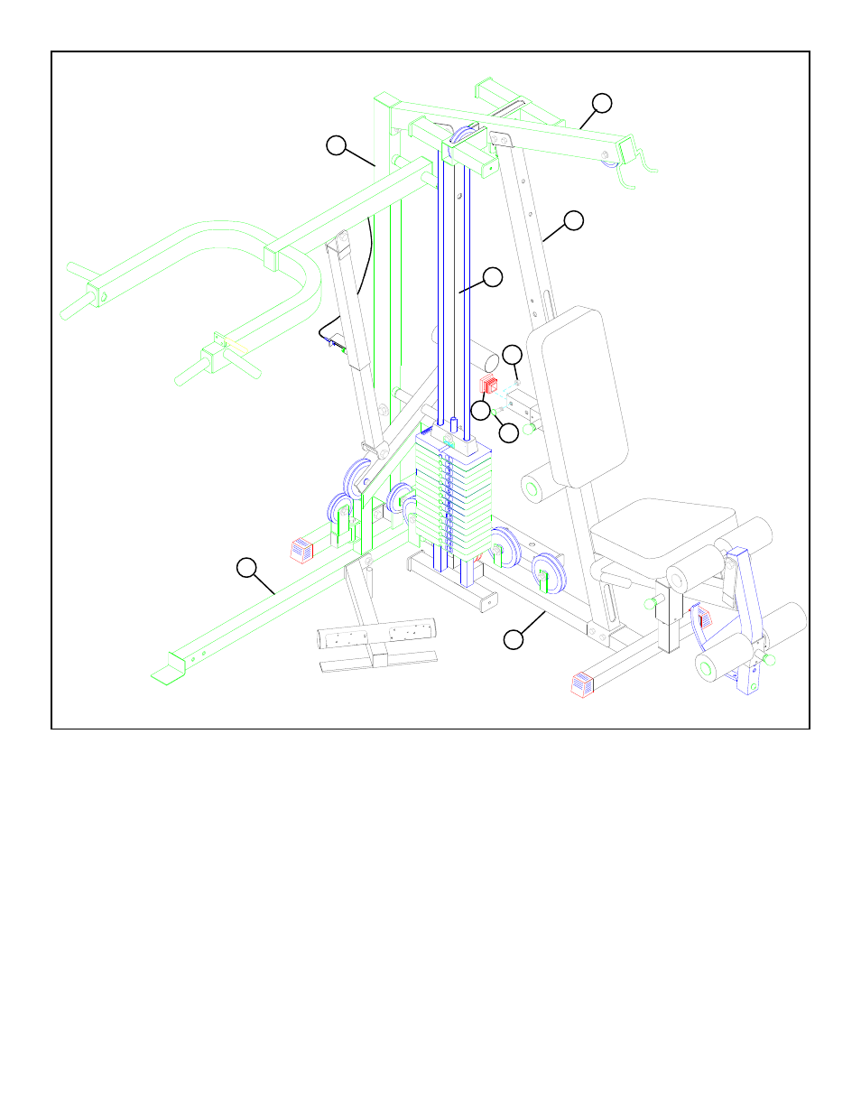
STEP 26
• SECURELY assemble one 3/8” X 1” BUTTON HEAD CAP SCREW (96) and one 3/8” LOCK NUT (92) to the last hole on the BACK
PAD ADJUST (16). See FIGURE 26.
FIGURE 26
• SECURELY insert one 2” SQ. END CAP (46) to the open end of the BACK PAD ADJUST (16). See FIGURE 26.
• SECURELY tighten all loose frame connections made to this point. (!!! IMPORTANT !!! to assure proper function of the 425,
the loose frame connections must be tightened in the following order) Tighten the:
• MIDDLE UPRIGHT (8) to the BASE (1) and to the TOP BOOM (17).
• REAR UPRIGHT (4) to the BASE (1) and to the TOP BOOM (17).
• PRESS BASE (18) to the REAR (4) and MIDDLE UPRIGHTS (8).
• PRESS BASE (18) to the BASE (1).
• FRONT UPRIGHT (25) to the BASE (1).
NOTE: DO NOT TIGHTEN THE FRONT UPRIGHT TO THE TOP BOOM AT THIS TIME.
92
46
96
8
25
4
1
17
18
BUTTON
HEAD
- Free Weight Systems (5 pages)
- 886101 (3 pages)
- 425/660 (2 pages)
- 822 (9 pages)
- 848101 (14 pages)
- 881 (26 pages)
- Free Weight Smith System (5 pages)
- Leg Press 100101 (14 pages)
- 360101 (11 pages)
- 777 (5 pages)
- 832102 (14 pages)
- Leg Press 100 (11 pages)
- 205101 (1 page)
- 425 (2 pages)
- 440 (33 pages)
- 426103 (45 pages)
- Hip Sled System (24 pages)
- 824 (8 pages)
- GS2 (24 pages)
- 826 (8 pages)
- 856 (6 pages)
- 400101 (27 pages)
- 829 (14 pages)
- 435104 (13 pages)
- GS6 (8 pages)
- 842 (6 pages)
- 778 (13 pages)
- 375101 (22 pages)
- Leg Press 5 (15 pages)
- 838 (10 pages)
- 441101 440 (10 pages)
- LP5 (15 pages)
- Home Guide (9 pages)
- 888 (15 pages)
- cm3 (8 pages)
- 870 (4 pages)
- 893103 (20 pages)
- 890 (10 pages)
- 250101 (18 pages)
- 843 (12 pages)
- GS4 (1 page)
- 849 (7 pages)
- 855 AB (9 pages)
- 883 (31 pages)