Figure 18 – ParaBody 425103 User Manual
Page 17
17
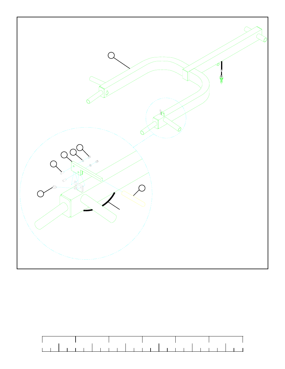
FIGURE 18
STEP 18
0
1
2
3
4
5
6
1/2
1/2
1/2
1/2
1/2
1/2
• Insert the PUSH/PULL CABLE through the bottom of the PRESS ARM (27) up to the CONTROL LEVER (60) and hold in place
with one E-RING (56) as shown in FIGURE 18.
• SECURELY assemble the PUSH/PULL CABLE to the CONTROL LEVER (60) using one 3/8” JOINT CONNECTOR CAP (57),
one #8 INT. TOOTH LOCK WASHER (59), and one 8-32 X 3/16 IN. SCREW (58) as shown in FIGURE 18.
• Slide one 4” VINYL SLEEVE (47) over the CONTROL LEVER (60). Then SECURELY assemble the CONTROL LEVER (60) to
the TAB on the PRESS ARM (27) using one 3/8” JOINT CONNECTOR CAP (57), one #8 INT. TOOTH LOCK WASHER (59),
and one 8-32 X 3/16 IN. SCREW (58) as shown in FIGURE 18.
59
PUSH/PULL
CABLE
27
58
60
57
56
47
See also other documents in the category ParaBody Sports and recreation:
- Free Weight Systems (5 pages)
- 886101 (3 pages)
- 425/660 (2 pages)
- 822 (9 pages)
- 848101 (14 pages)
- 881 (26 pages)
- Free Weight Smith System (5 pages)
- Leg Press 100101 (14 pages)
- 360101 (11 pages)
- 777 (5 pages)
- 832102 (14 pages)
- Leg Press 100 (11 pages)
- 205101 (1 page)
- 425 (2 pages)
- 440 (33 pages)
- 426103 (45 pages)
- Hip Sled System (24 pages)
- 824 (8 pages)
- GS2 (24 pages)
- 826 (8 pages)
- 856 (6 pages)
- 400101 (27 pages)
- 829 (14 pages)
- 435104 (13 pages)
- GS6 (8 pages)
- 842 (6 pages)
- 778 (13 pages)
- 375101 (22 pages)
- Leg Press 5 (15 pages)
- 838 (10 pages)
- 441101 440 (10 pages)
- LP5 (15 pages)
- Home Guide (9 pages)
- 888 (15 pages)
- cm3 (8 pages)
- 870 (4 pages)
- 893103 (20 pages)
- 890 (10 pages)
- 250101 (18 pages)
- 843 (12 pages)
- GS4 (1 page)
- 849 (7 pages)
- 855 AB (9 pages)
- 883 (31 pages)