Figure 20 – ParaBody 425103 User Manual
Page 19
19
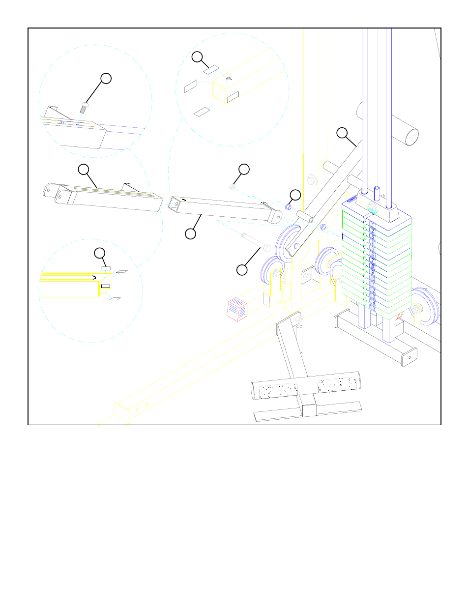
FIGURE 20
STEP 20
• CAREFULLY slide the PRESS ADJUSTMENT TUBE (22) into the RECEIVING TUBE (13). (NOTE: Make sure the spring pin
barrel on the RECEIVING TUBE (13) is on the same side as the holes in the PRESS ADJUSTMENT TUBE (22).)
• Attach eight PARAGLIDE STRIPS (62) INSIDE the end of the RECEIVING TUBE (13) and four PARAGLIDE STRIPS (62) to
the OUTSIDE of the PRESS ADJUSTMENT TUBE (22) using the following steps:
• Thoroughly clean all sufaces where PARAGLIDE STRIPS (62) are to be attached.
• Remove the PARAGLIDE STRIPS (62) from the paper backing and firmly apply them to surfaces. (NOTE: Orientate the
strips so they will slide by each other.)
• Insert two 1/2” FLANGE BEARINGS (78) into the COUNTER LEVER (3) as shown in FIGURE 20.
• Assemble the PRESS ADJUSTMENT TUBE (22) to the COUNTER LEVER (3) using one 1/2 X 3-1/2” BOLT (90) and one 1/2”
LOW HEIGHT LOCK NUT (95). (NOTE: Tighten the connection enough to remove play, yet allowing the PRESS AD-
JUSTMENT TUBE (22) to rotate freely.)
1/2 X 3-1/2” 90
3
78
22
62
13
62
95 LOW
HEIGHT
NUT
• Thread one 3/8 X 1” BUTTON HEAD CAP SCREW (96) through the slot in the RECEIVING TUBE (13) and into the ADJUSTMENT
TUBE (22)
96 3/8 X 1”
BUTTON HD
CAP SCREW