Porter-Cable CPFC2TV3525VP User Manual
Page 11
11 - ENG
N015840
DESCRIPTION OF OPERATION
Become familiar with these controls before operating the unit.
Auto(I)/Off(O) Switch: Place this switch in the "Auto (I)" position to provide auto-
matic power to the pressure switch and "Off (O)" to remove power at the end of
each use.
Pressure Switch: The pressure switch automatically starts the motor when the
air tank pressure drops below the factory set "cut-in" pressure. It stops the motor
when the air tank pressure reaches the factory set "cut-out" pressure.
Safety Valve: If the pressure switch does not shut off the air compressor at its
"cut-out" pressure setting, the safety valve will protect against high pressure by
"popping out" at its factory set pressure (slightly higher than the pressure switch
"cut-out" setting).
Outlet Pressure Gauge: The outlet pressure gauge indicates the air pressure
available at the outlet side of the regulator. This pressure is controlled by the regula-
tor and is always less than or equal to the tank pressure.
Tank Pressure Gauge: The tank pressure gauge indicates the reserve air pressure
in the tank.
Regulator: Controls the air pressure shown on the outlet pressure gauge. Pull
the knob out and turn clockwise to increase pressure and counterclockwise to
decrease pressure. When the desired pressure is reached push knob in to lock in
place.
Universal Quick-Connect Body: The universal quick-connect body accepts the
three most popular styles of quick-connect plugs- Industrial, automotive (Tru-flate),
and ARO. One hand push-to-connect operation makes connections simple and
easy.
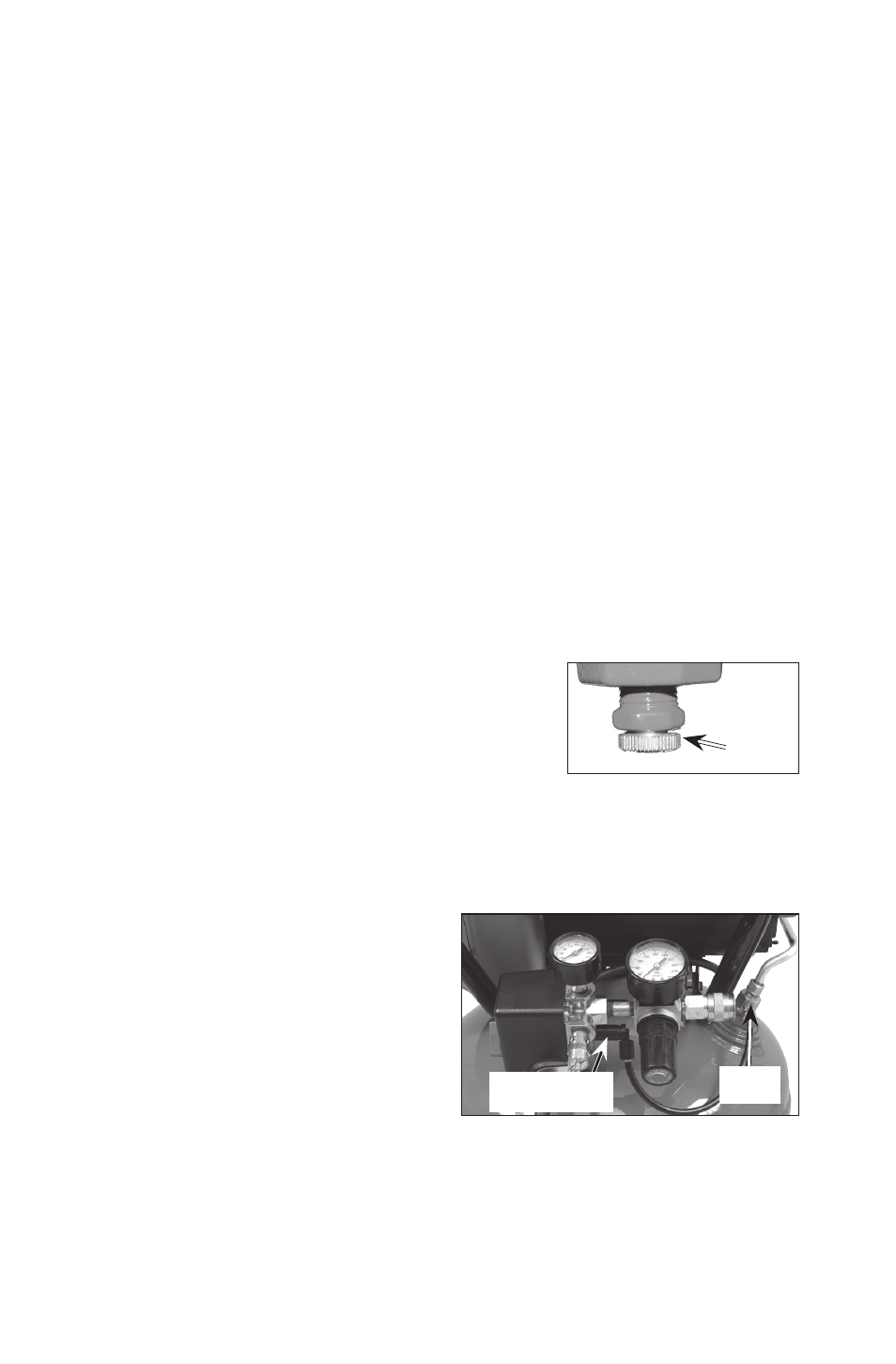
Drain Valve: The drain valve is located at the base of
Drain
Valve
the air tank and is used to drain condensation at the
end of each use.
Cooling System (not shown): This compressor
contains an advanced design cooling system. At the
heart of this cooling system is an engineered fan. It is
perfectly normal for this fan to blow air through the vent holes in large amounts. You
know that the cooling system is working when air is being expelled.
Air Compressor Pump (not shown): Compresses air into the air tank. Working
air is not available until the compressor has raised the air tank pressure above that
required at the air outlet.
Check Valve: When the air compressor is
Pressure
Release Valve
Check
Valve
operating, the check valve is "open",
allowing compressed air to enter the air
tank. When the air compressor reaches
"cut-out" pressure, the check valve "clos-
es", allowing air pressure to remain inside
the air tank.
Pressure Release Valve: The pressure
release valve located on the side of the
pressure switch, is designed to automati-
cally release compressed air from the compressor head and the outlet tube when
the air compressor reaches "cut-out" pressure or is shut off. The pressure release
valve allows the motor to restart freely. When the motor stops running, air will be
heard escaping from this valve for a few seconds. No air should be heard leak-
ing when the motor is running, or continuous leaking after unit reaches "cut-out"
pressure.