5 video port, 6 ethernet connectors – PC Concepts SHG2 DP User Manual
Page 80
Connections
Intel® SHG2 DP Server Board Technical Product Specification
Intel Order Number C11343-001
Revision 1.0
68
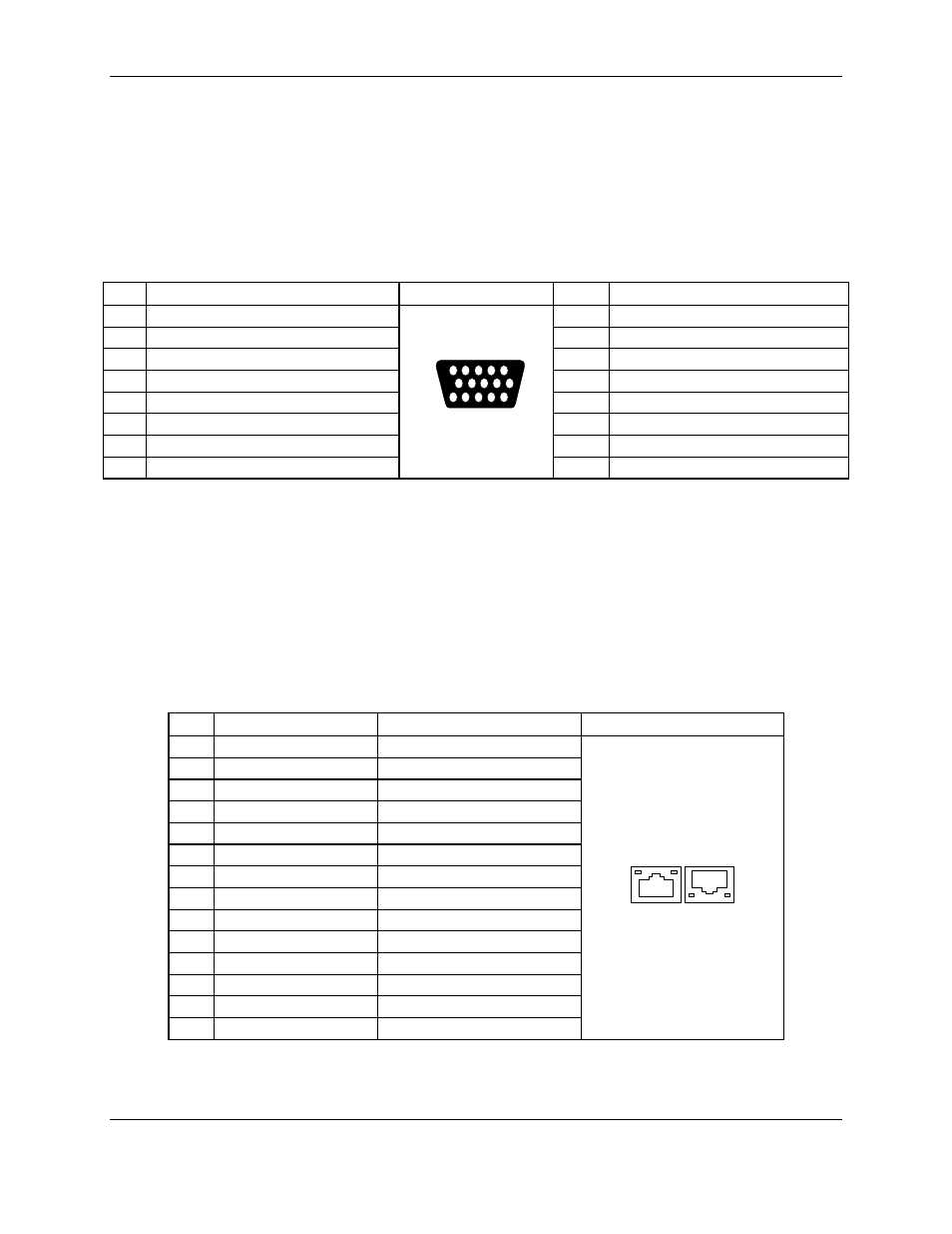
8.10.5 Video
Port
The video port interface is a standard VGA-compatible 15-pin connector. An ATI Rage XL
video controller, with 8 MB of onboard video SDRAM, supplies on-board video.
Table 54. Video Connector
[Key-H]
Pin Signal Video
Connector
Pin Signal
1
GRED+10 (analog color signal R)
9
5 V
2
GGREEN+10 (analog color signal G)
10
GND
3
GBLUE+10 (analog color signal B)
11
No connection
4 No
connection
12 SDA
–10
5
GND
13
GHSYNC+10 (horizontal sync)
6
GND
14
GVSYNC+10 (vertical sync)
7 GND
15 SCL
-10
8 GND
5
1
15
11
6
10
8.10.6 Ethernet
Connectors
[Key – I & J] The system supports two onboard network interface controllers, one 10/100
Mbps (NIC-1) and one 10/100/1000 Mbps (NIC-2) These Ethernet connectors are each single
RJ-45 connectors with integrated activity / link and speed / status LEDs.
Table 55. Ethernet Connectors
[Key-I & J]
Pin
NIC1 Signal (10/100)
NIC2 Signal (10/100/1000)
Ethernet Connectors
1
L1TD +
TR0 +
2 L1TD
–
TR0
–
3 GND
TR1
+
4
Chassis GND
TR1 –
5
Chassis GND
2.5V VCC
6 GND
2.5V
VCC
7
L1RD +
TR2 +
8 L1RD
–
TR2
–
9
LAN1_ACTIVE_LED +
TR3 +
10
LAN1_LINK_LED +
TR3 –
11 LAN1_SPEED_LED LAN2_ACTIVE_LED
12
3 V Standby
LAN2_LINK_LED
13 Chassis
GND
PSLED_YELLOW
14 Chassis
GND
PSLED_GREEN
NIC2
NIC1
The 82550PM drives LEDs on the network interface connector that indicate transmit/receive
activity on the LAN, a valid link to the LAN, and 10- or 100-Mbps operation. The green LED