2 system reset control – PC Concepts SHG2 DP User Manual
Page 43
Intel® SHG2 DP Server Board Technical Product Specification
Server Management
Revision 1.0
Intel Order Number C11343-001
31
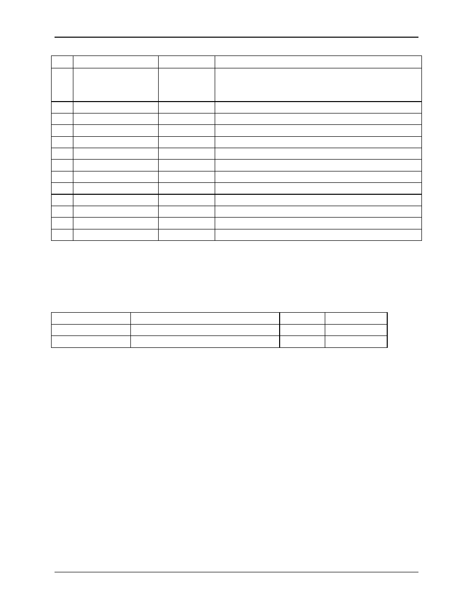
Pin
ADM1026 Signal Name
Type
External Signal Name / Function
active low output with a 200 ms minimum pulse width. This is
asserted whenever 3.3VSTBY is below the reset threshold. It
remains asserted for approx. 200ms after 3.3VSTBY rises
above the reset threshold.
30
P5VIN
Analog Input
VP50 / Monitors +5 V supply
31
N12VIN
Analog Input
XN12 / Monitors -12 V supply
32
P12VIN
Analog Input
XP12 / Monitors +12 V supply
33
VCCP
Analog Input
VCC_P / Monitors processor core voltage (0 to 3.0 V)
34
AIN7
Analog Input
ADM_VCC25 / Monitors +2.5V supply
35
AIN6
Analog Input
VDD15 / Monitors VTT supply
43
GPIO15
Digital Input
CPU2_THERMTRIPN / CPU2 Thermal Trip
44
GPIO14
Digital Input
CPU1_THERMTRIPN / CPU1 Thermal Trip
45
GPIO13
Digital Input
CPU2_PROCHOTN / CPU2 Processor Hot
46
GPIO12
Digital Input
CPU1_PROCHOTN / CPU1 Processor Hot
47
GPIO11
Digital Input
SC1TERMOFF+00 / SCSI Channel A Termination Off
48
GPIO10
Digital Input
SC2TERMOFF+00 / SCSI Channel B Termination Off
Eight-bit ‘analog’ readings for the following system temperatures are provided, described in
Table 19.
Table 19. Temperature Sensors
Temperature Sensor
Description
Resolution
Accuracy
Primary Processor
Primary processor socket thermal sensor
8-bit
+/- 5°C or better
Secondary Processor
Secondary processor socket thermal sensor
8-bit
+/- 5°C or better
5.2 System Reset Control
Reset circuitry on the Intel SHG2 server board looks at resets from the front panel, CSB5, in-
target probe (ITP), and the processor subsystem to determine proper reset sequencing for all
types of resets. The reset logic is designed to accommodate a variety of ways to reset the
system, which can be divided into the following categories:
•
Power-up reset
•
Hard reset
•
Soft (programmed) reset
The following subsections describe each type of reset.
5.2.1 Power-up
Reset
When the system is disconnected from AC power, all logic on the server board is powered off.
When a valid input (AC) voltage level is provided to the power supply, 3.3-volt standby power
will be applied to the server board. A power monitor circuit on 3.3-volt standby will assert
BMCRST_L, causing the BMC to reset. The BMC is powered by 3.3 volt standby and monitors
and controls key events in the system related to reset and power control.