Baseboard pci i/o subsystem, 1 overview – PC Concepts SHG2 DP User Manual
Page 30
Baseboard PCI I/O Subsystem
Intel® SHG2 DP Server Board Technical Product Specification
Intel Order Number C11343-001
Revision 1.0
18
3. Baseboard PCI I/O Subsystem
3.1 Overview
The I/O buses for the Intel SHG2 server board are both PCI-X and PCI, with one PCI and two
PCI-X bus segments or peers.
All the PCI (-X) buses comply with the PCI Local Bus
Specification, Revision 2.2 and PCI-X Specification, Revision 1.0a.
All three 64-bit slots on
SHG2 are capable of supporting PCI-X mode (note: the 7899 on-board SCSI adapter must be
disabled in BIOS Setup to enable PCIX-6 support of PCI-X mode).
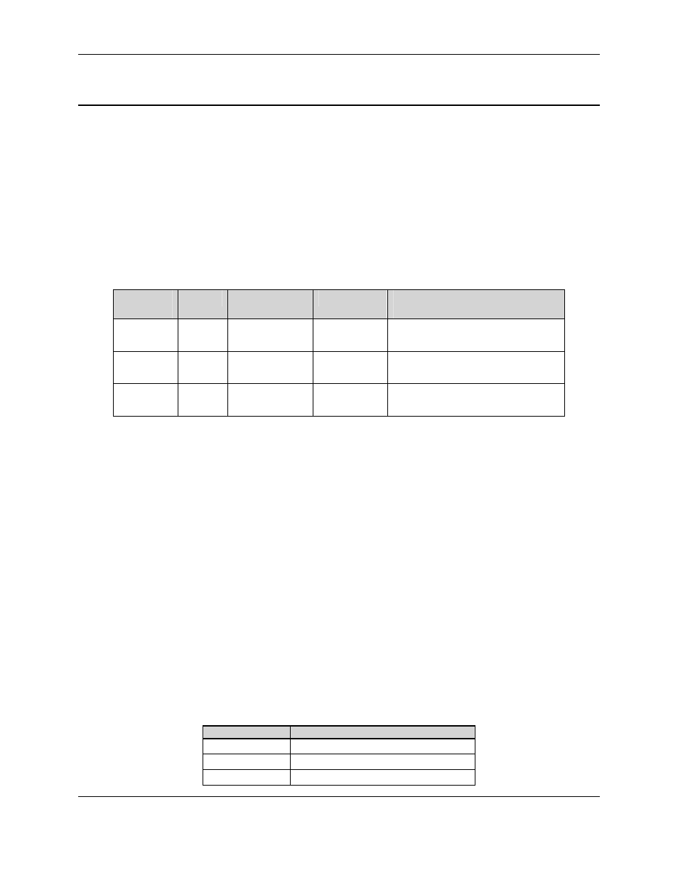
Table 9 lists the
characteristics of the three PCI (-X) bus segments.
Table 9. PCI(-X) Bus Segment Characteristics
PCI Bus
Segment
Width
Speed
Type
Add-in PCI Slot Support,
Total Eight Slots
64/100MHz
64 bit
100MHz
PCI-X
2 slots (64-bit/100-MHz)
Full-length cards supported
64/133MHz
64 bit
133 MHz
PCI-X
1 slots (64-bit/133-MHz)
Full-length cards supported
32/33MHz
32 bit
33 MHz
PCI
3 slots (32-bit 33-MHz)
Full-length cards supported
3.2 64-bit/100MHz PCI-X Subsystem
64/100 MHz segment supports these embedded devices and connectors:
•
Two 184-pin, 3.3 V, 64-bit PCI (-X) expansion connectors, numbered PCIX-1 (64/100)
and PCIX-2 (64/100).
•
One embedded 82544GC Gigabit Ethernet Controller.
3.2.1
Device IDs (IDSEL)
All slots on this segment support PCI (X) and conform to the PCI-X Specification, Revision
1.0a.
Each device under the PCI-X host bridge has its IDSEL signal connected to one bit of
AD[31::16], which acts as a chip select on the PCI(-X) bus segment.
This determines a unique
PCI (-X) device ID value for use in configuration cycles.
Table 10 shows both the bit to which
each IDSEL signal is attached for 64/100MHz devices, and the corresponding device number.
Table 10. 64/100MHz Segment Configuration IDs
IDSEL Value
Device
25
PCI (X) Slot #1, PCIX-1 (64/100)
24
PCI (X) Slot #2, PCIX-2 (64/100)
20
82544GC Gigabit Ethernet Controller