6 interrupt routing – PC Concepts SHG2 DP User Manual
Page 35
Intel® SHG2 DP Server Board Technical Product Specification
Baseboard PCI I/O Subsystem
Revision 1.0
Intel Order Number C11343-001
23
640x480 60,72,75,90,100
Supported Supported Supported Supported
800x600 60,70,75,90,100
Supported Supported Supported Supported
1024x768
60,72,75,90,100
Supported Supported Supported Supported
1280x1024 43,60,70,72
Supported
Supported
–
–
1600x1200 60,66,76,85
Supported
–
–
–
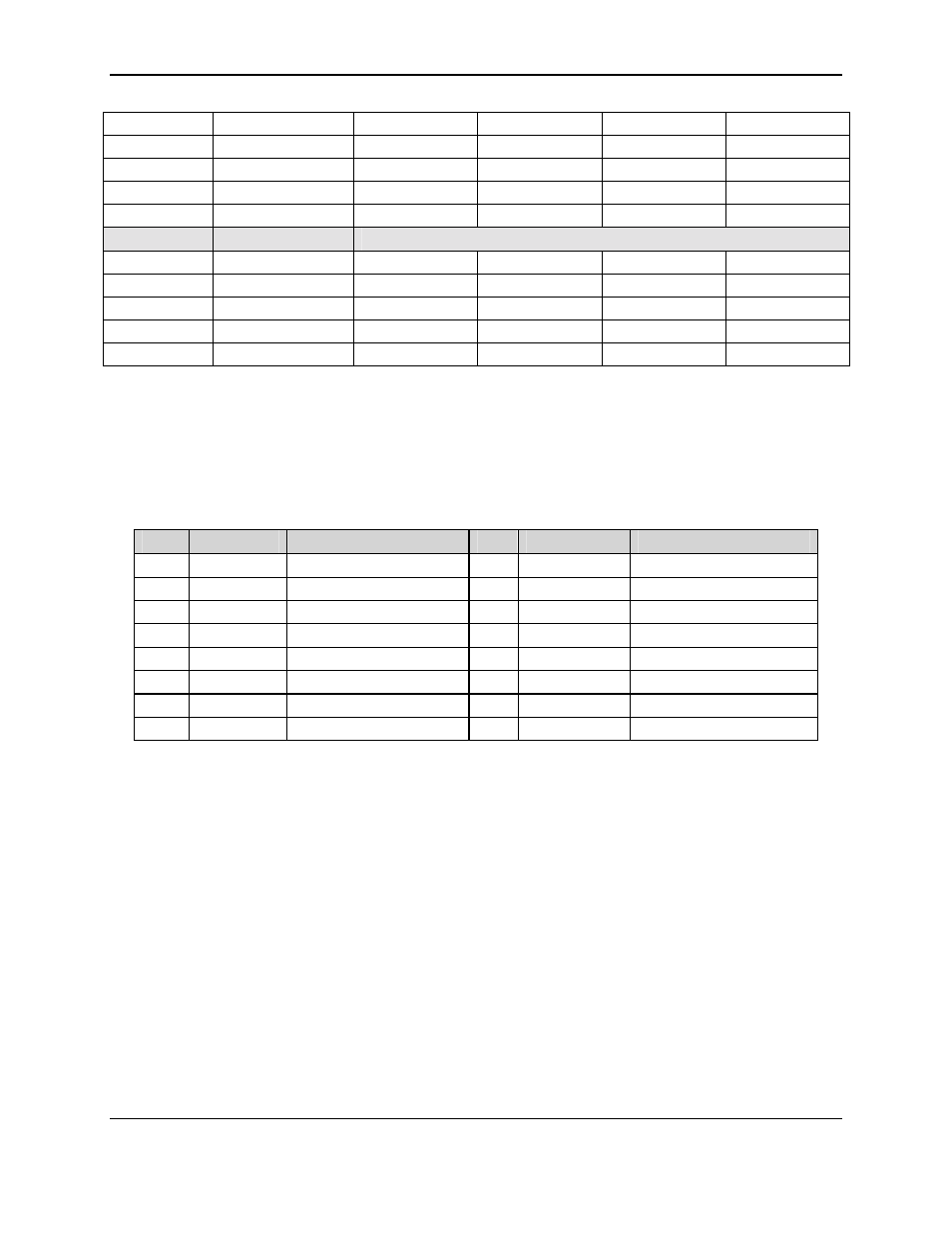
3D Mode
Refresh Rate (Hz)
SHG2 3D Video Mode Support with Z Buffer Disabled
640x480 60,72,75,90,100
Supported Supported Supported Supported
800x600 60,70,75,90,100
Supported Supported Supported Supported
1024x768
60,72,75,90,100
Supported Supported Supported Supported
1280x1024
43,60,70,72 Supported Supported Supported –
1600x1200 60,66,76,85
Supported
Supported
–
–
3.5.4.2 VGA
Connector
Table 17 shows the pinout of the VGA connector.
For more information, see the ATI RAGE XL
Technical Reference Manual.
Table 17. Video Port Connector Pinout
Pin
Signal
Description
Pin
Signal
Description
1
RED
Analog color signal R
9
VREF
Video Power
2
GREEN
Analog color signal G
10
GROUND
Video ground
3
BLUE
Analog color signal B
11
N/C
No connect
4
N/C
No connect
12
DDCDAT
Monitor ID data
5
GROUND
Video ground (shield)
13
HSYNC
Horizontal Sync
6
GROUND
Video ground (shield)
14
VSYNC
Vertical Sync
7
GROUND
Video ground (shield)
15
DDCCLK
Monitor ID clock
8
GROUND
Video ground (shield)
3.6 Interrupt
Routing
SHG2 interrupt architecture accommodates both a PC-compatible Programmable Interrupt
Controller (PIC) mode and APIC mode interrupts through use of the integrated I/O APICs in the
CSB5. Figure 4 shows the PIC mode interrupt routing supported in the SHG2 baseboard.
Figure 5 shows the symmetric mode interrupt routing supported in the SHG2 baseboard.