Removal of control board – Panasonic CU-TE12DKE User Manual
Page 67
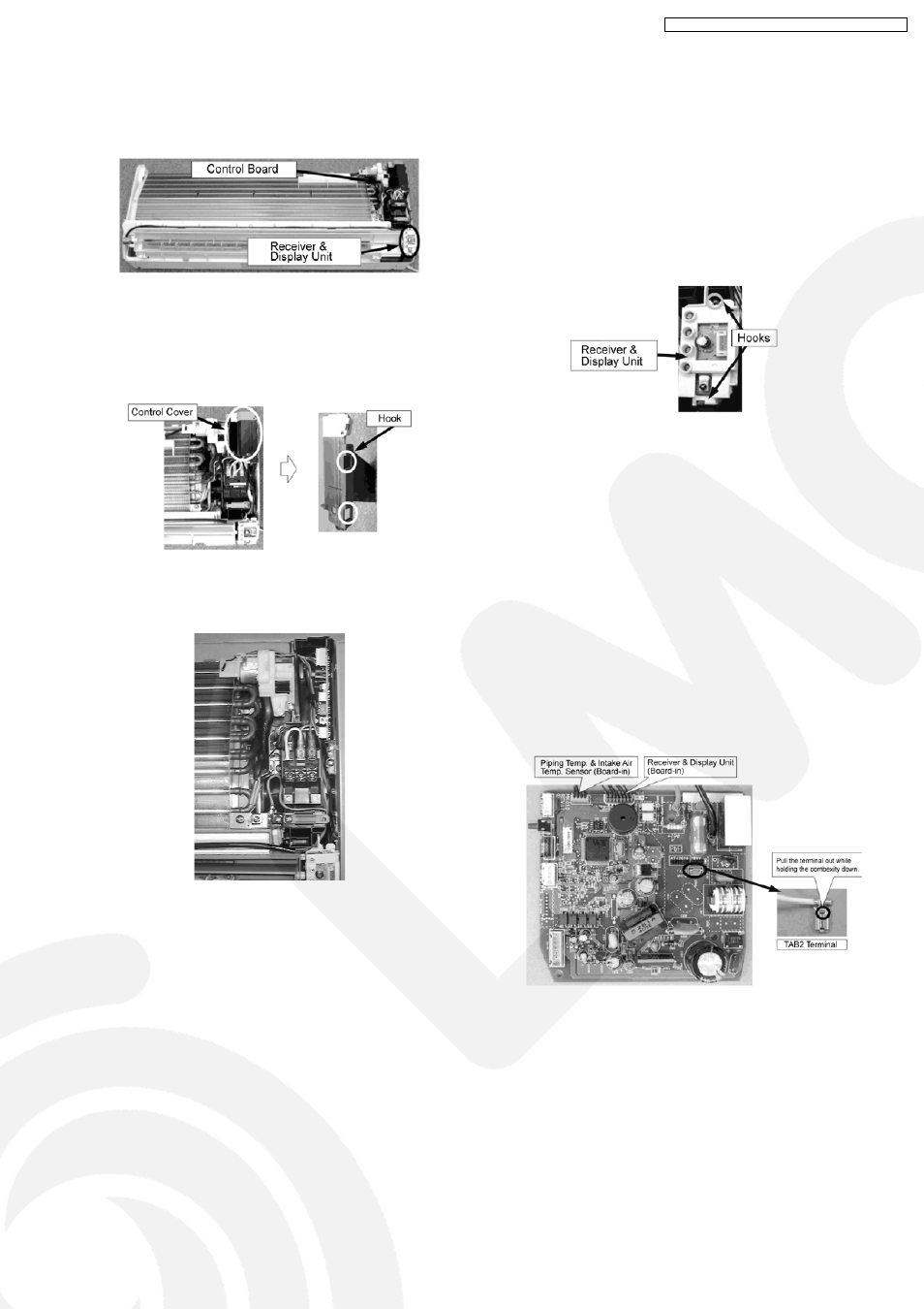
13.4.1.3. Removal of Control Board
1. Remove the Front Panel according to the item 13.5.1.1.
2. Remove the Front Grille according to the item 13.5.1.2.
Fig. 7
3. Remove the Control Cover.
Note for Disassembly:
There are hooks on both sides (left and right).
Fig. 8
4. Pull out the Control Board.
Fig. 9
5. Remove a variety of Connectors and Terminals.
Wiring parts from the upper side
•
•
•
•
CN-STM2 (blue) ...... Front Panel Open/Close Motor
•
•
•
•
CN-TH (yellow) ...... Intake Air / Pipe Temp. Sensor
Note for Disassembly:
The CN-TH (yellow) can not be disconnected.
Disconnect thermosensitive part of the Pipe Temp.
Sensor from the holder (Board-in). The Intake Air
Temp. Sensor can be easily disconnected.
Wiring cables from lower side
•
•
•
•
CN-STM1 (White) ...... Air Swing Motor for Vertical
Louver
•
•
•
•
CN-FM (White) ...... Indoor Fan Motor
•
•
•
•
CN-ION (White) ...... Ionizer
•
•
•
•
CN-DISP (green or yellow) ...... Control Board
(Receiver & Display Unit)
Note for Disassembly:
The CN-TH (yellow) can not be disconnected
from Control Board. Remove whole plastic part
by releasing the hooks (two) for the Receiver &
Display Unit (Board-in).
Fig. 10
Note for Disassembly:
Disconnect the connectors while holding the
hooks down. Do not pull it out directly.
Wiring cables from the Terminal Board
•
•
•
•
TAB1 terminal (brown) ...... Disconnect the terminal.
•
•
•
•
TAB2 terminal (white) ...... Disconnect the terminal.
Note for Disassembly:
Disconnect
the
terminals
while
holding
the
convexity down in the center of each terminal.
•
•
•
•
H1 (black), H3 (red) are soldered on PCB. .........
Remove it from the PCB by desoldering.
Fig. 11
67
CS-TE9DKE CU-TE9DKE / CS-TE12DKE CU-TE12DKE