Alarm input installation – Pelco Dx8000 User Manual
Page 22
22
C623M-C (3/05)
ALARM INPUT INSTALLATION
The DX8000 has either 8 or 16 dry contact alarm inputs, depending on your system’s configuration. Each input is programmed to function as
either a normally open or normally closed circuit.
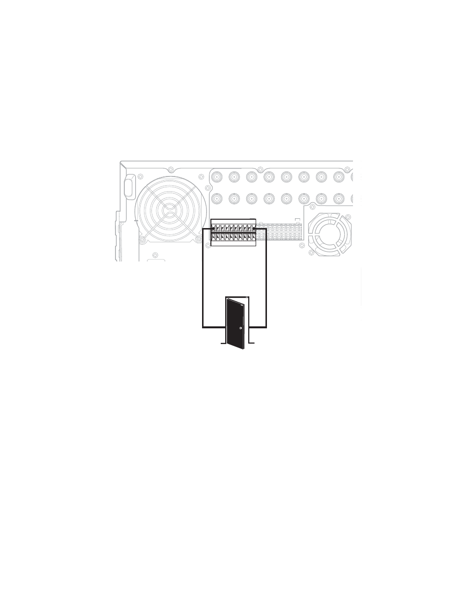
To wire an alarm input:
1. Insert the green terminal blocks into the alarm sockets on the back panel of the recorder.
2. Connect one wire from the source device to one of the sensor input terminals 1 through 16.
3. Connect a second wire from the source device to a GND terminal.
4. Refer to the Operation/Programming manual for information on how to program the alarm inputs.
Figure 13. Alarm Terminal Installation
IN1
IN2
IN3
IN4
IN5
IN6
IN7
IN8
IN9
IN9
IN10
IN11
IN12
IN13
IN14
IN15
IN16
OUT16
OUT15
OUT14
OUT13
OUT12
OUT11
OUT10
OUT9
OUT9
OUT8
OUT7
OUT6
OUT5
OUT4
OUT3
OUT2
OUT1
ALARM INPUTS
RELAY OUTPUTS
1
2 2 4 5 6 7 8 GND
9 10 11 12 13 14 15 16
1
2 2 4 5 6 7 8 GND
9 10 11 12 13 14 15 16
9 10 11 12 13 14 15 16
CRT
ALARM
OUTPUT 1
GND